
Electric powered vehicle

a technology of electric vehicles and electric motors, applied in the direction of electric propulsion mounting, cycle equipment, cycle, etc., can solve the problems of increasing the weight of the vehicle body, increasing the number of manufacturing processes, increasing the weight of the vehicle, etc., and achieve the effect of reducing the ease of mounting

Inactive Publication Date: 2005-10-06
HONDA MOTOR CO LTD
View PDF3 Cites 43 Cited by
  • Summary
  • Abstract
  • Description
  • Claims
  • Application Information

AI Technical Summary

Benefits of technology

The present invention is about an electric vehicle that uses an electric motor powered by a battery. The vehicle has a unique design that includes a head pipe with a steerable handlebar, a front frame, an intermediate frame, and a rear frame. A partition plate and a battery housing part are also included. The design allows for a more efficient use of space, reduces the number of parts, and allows for a larger battery size. The vehicle also has a unique form that restrains the lateral movement of the battery. Overall, the invention provides a more efficient and compact electric vehicle with improved battery performance.

Problems solved by technology

Thus, both the manufacturing cost and the number of processes thereof are increased.
In addition, the weight of the vehicle body is increased because of the necessity of providing a battery case having sufficient rigidity for mounting a heavy object such as the battery, and the necessity of a rigid connecting member between the case and the vehicle frame.
Hence, the increase in vehicle weight provides a technical problem.

Method used


Image

  • Electric powered vehicle
  • Electric powered vehicle
  • Electric powered vehicle

Examples


Embodiment Construction

[0030] A preferred embodiment mode of the present invention is described hereinbelow with reference to the drawings.

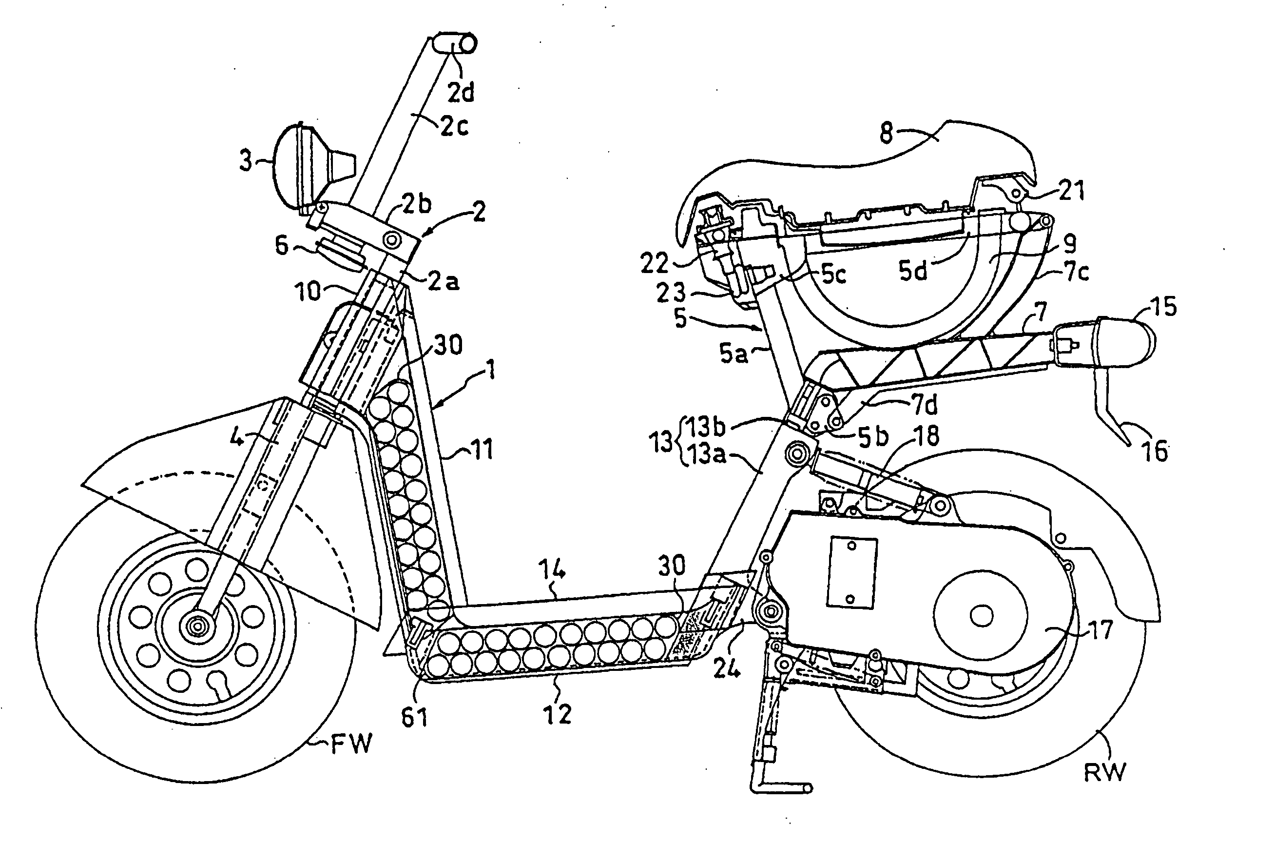
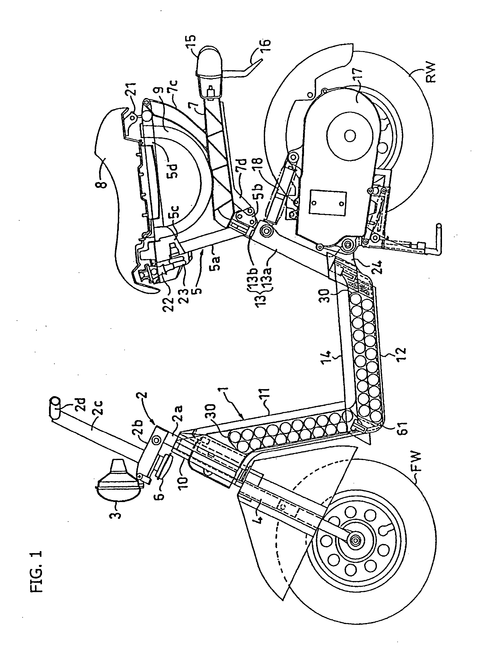
[0031] Referring first to FIG. 1, which is an overall side view of a scooter type electric powered motorcycle according to the present invention, a body frame 1 forms a frame for the vehicle. The body frame 1 includes a head pipe 10, a front frame 11 which extends diagonally downward toward the rear of the vehicle from the head pipe 10, an intermediate frame 12 which is bent toward the rear of the vehicle at the bottom end of the front frame 11 and which is substantially horizontally extending toward the rear of the vehicle, and a rear frame 13 which passes through the rear end of the intermediate frame 12 and which extends diagonally upward toward the rear of the vehicle. Each of these frames 11, 12, 13 is formed through processing of a highly rigid metal member. A battery package 30, which is described later, is housed in each of the intermediate frame 12 and the fr...


PUM


Abstract

An electric powered vehicle which is powered by an electric motor via a battery, includes a front frame which extends diagonally downward toward the rear of the vehicle from the head pipe, an intermediate frame which is bent toward the rear of the vehicle at the bottom end of the front frame and which is substantially horizontally extending toward the rear of the vehicle, and a rear frame which extends from the intermediate frame diagonally upward toward the rear of the vehicle. A front portion of the intermediate frame includes a partition plate extending diagonally upward toward the rear. The battery is retained within the intermediate frame, and restrained from motion in the longitudinal direction, by the partition plate and the rear frame. This structure provides an electric powered vehicle whose battery is effectively and removably mountable on the body frame in a limited space thereof.

Description

CROSS-REFERENCE TO RELATED APPLICATIONS [0001] The present invention claims priority under 35 USC 119 based on Japanese patent application No. 2004-102142, filed on Mar. 31, 2004. The subject matter of this priority document is incorporated by reference herein. BACKGROUND OF THE INVENTION [0002] 1. Field of the Invention [0003] The present invention relates to an electric powered vehicle, and more particularly to an electric powered vehicle whose battery is efficiently and removably mountable on the body frame in a limited space thereof. [0004] 2. Background of the Invention [0005] In addition to a conventional motorcycle whose drive source is an internal combustion engine, research has been conducted on an electric motorcycle whose drive source is an electric motor. In this vehicle, the electric motor is powered using a battery. In such an electric motorcycle, since the ratio of a battery weight to the total weight of a vehicle body is large, the mounting position of the battery be...

Claims


Application Information

Patent Timeline
Patent Type & Authority Applications(United States)
IPC IPC(8): B62K11/10B60K1/00B60K1/04B60L11/18B62J11/00B62K11/00B62K11/02B62K19/30B62M7/12
CPCB60K1/04B62M7/12B62K2204/00B62K2202/00
Inventor YONEHANA, ATSUSHIOKUDA, TAKU
Owner HONDA MOTOR CO LTD
Learn More