Fluid filter apparatus and method

Active Publication Date: 2005-10-06
NATURAL CHOICE CORP
View PDF26 Cites 4 Cited by
  • Summary
  • Abstract
  • Description
  • Claims
  • Application Information

AI Technical Summary

Benefits of technology

[0015] The cartridge also includes a closure member. The closure member is integrally formed with the filter housing. The housing, in some aspects of the present invention, may be tapered, to ease proper installation.
[0018] Each level of the closure member also includes at least one boss or tab. This boss or tab has at least one ramped face in the depicted embodiments. The bosses are fabricated and oriented to engage the inlet and outlet stop projections when the cartridge is installed in the manifold seat. The bosses are further fabricated and oriented in relation to one another so that upon installation, the outlet stop is engaged to open first and the inlet stop is engaged to open last. Thus, on installation, the outlet valve is already open when the inlet valve is opened, avoiding pressure shocks to the filter alignment and avoiding leakage. The order is reversed when the cartridge is being removed. The bosses close the fluid intake stop valve first, and close the fluid outlet stop second, also suppressing leakage and discontinuous pressure transitions.
[0020] Separately from the stop valve actuation bosses, the closure member and manifold further have ramped lugs dimensioned to cooperate with each other. These mounting lugs thread together to provide for a 90° turn screw fit. The inlet ports, stop valve bosses and mounting lugs are oriented symmetrically, so that a single, simple twisting motion will mount the cartridge in the manifold. Another boss and detent on the ramped lugs provide a positive stop, imparting a desirable “snap” sensation to a user, confirming proper installation.

Problems solved by technology

The alternative design not having a removable base, the cartridge may be removed and replaced from the manifold of the filter system, but the filter may not be replaced within the cartridge housing.

Method used


Image

  • Fluid filter apparatus and method
  • Fluid filter apparatus and method
  • Fluid filter apparatus and method

Examples


Embodiment Construction

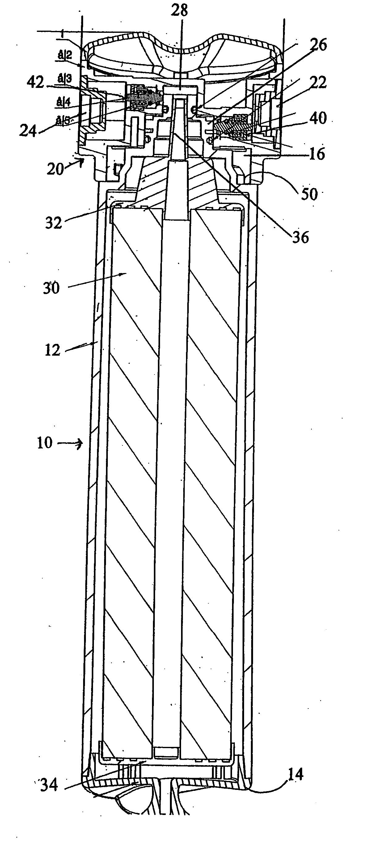
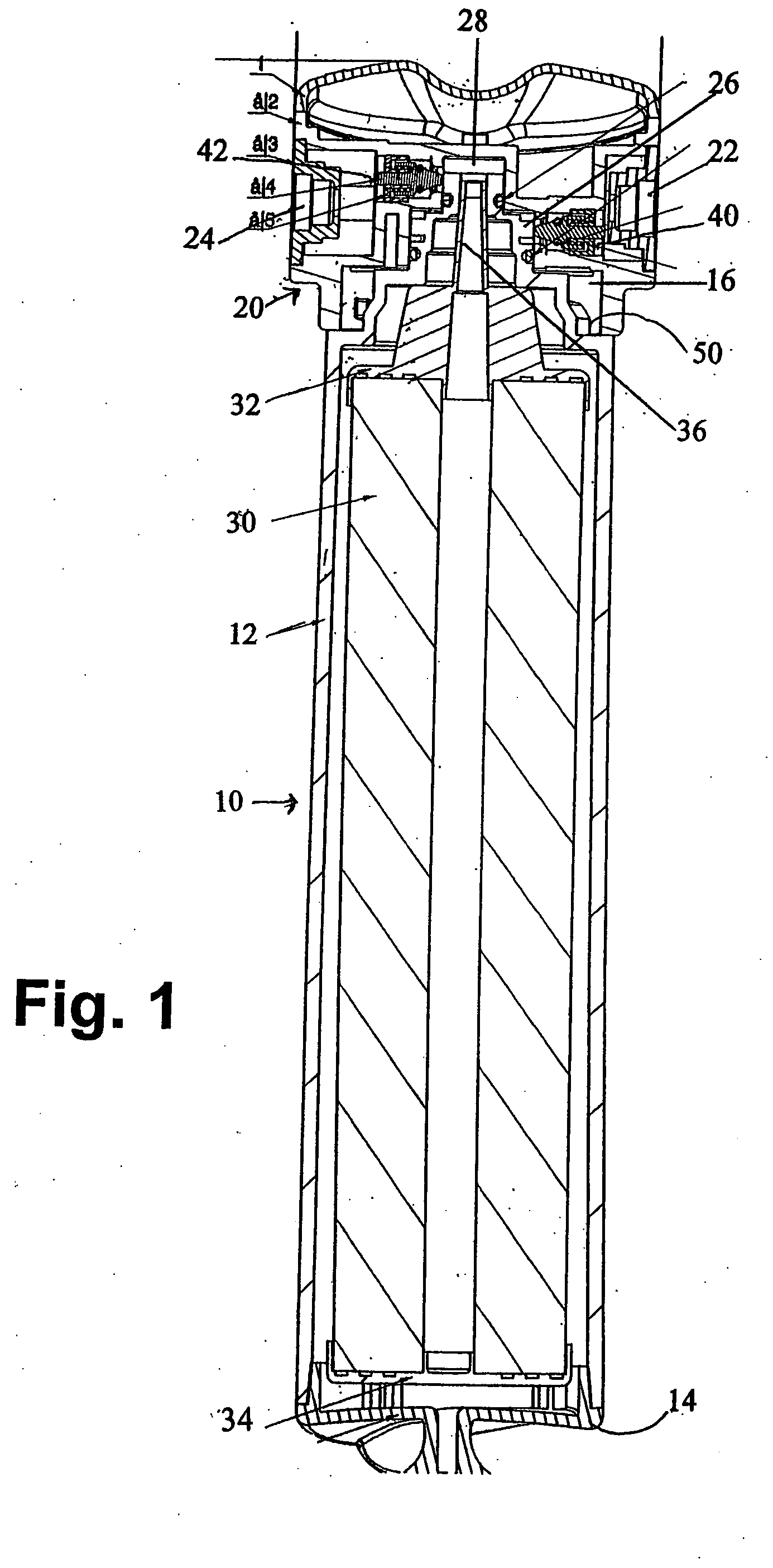
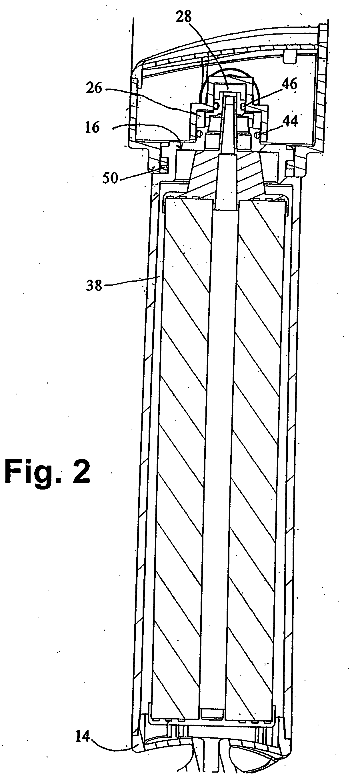
[0039] Referring to the accompanying drawings in which like reference numbers refer to like elements, FIG. 1 is a cutaway front view of the fluid filter manifold and cartridge assembly of the present invention. FIG. 2 is a cutaway side view of the same. Cartridge 10 is depicted as installed in manifold 20. The aspects of cartridge 10 include housing 12 base 14 and a closure member, indicated generally at 16.

[0040] Manifold 20 includes a fluid intake 22 and a fluid output 24. Intake 22 and output 24 are adapted to be installed with standard plumbing fittings in manners that will be recognized by those with skill in the art. Within manifold 20 are a first seat level 26 and second seat level 28.

[0041] Inside the housing 12 are a filter 30 assembled with a filter end cap 32 and filter base 34. The filter end cap 32 has a projecting filter output tube 36. In the depicted embodiment, a space 38 is provided between housing wall 12 and filter 30 for water flow. It is within the scope of t...


PUM

PropertyMeasurementUnit
Angleaaaaaaaaaa
Lengthaaaaaaaaaa
Angleaaaaaaaaaa

Abstract

A fluid filter system has a manifold having a fluid inlet with an inlet stop and a fluid outlet with an outlet stop and a cartridge seat. A cartridge is separable from the manifold and adapted to mount and dismount in the manifold. The cartridge has a filter housing containing a filter for filtering fluid, and an integral closure member having a first level and a second level. A radial inlet port is on a face of the first level of the closure member and an axial outlet port is on top of the second level of the closure member. A first boss on the closure member opens the inlet stop when the cartridge is mounted in the manifold. A second boss on the closure member is disposed to open the outlet stop when the cartridge is mounted in the manifold. The bosses engage the stops sequentially.

Description

CROSS-REFERENCE TO RELATED APPLICATIONS [0001] None. STATEMENT REGARDING FEDERALLY SPONSORED RESEARCH OR DEVELOPMENT [0002] Not Applicable. BACKGROUND OF THE INVENTION [0003] 1. Field of the Invention [0004] The present invention is a fluid filter cartridge, manifold and method for their assembly and for replacing cartridges. [0005] 2. Related Art [0006] Fluid filters, particularly water filters, are known. Drinking water filters adapted for use with plumbing in buildings where people work or live is common in many areas. A variety of filter types can be used, including charcoal, other granular types of filters or pleated membranes and the like. After any filter has been used for a period of time, it becomes less effective as impurities build up within it. Accordingly, filter systems need to provide for filter replacement. [0007] U.S. Pat. No. 5,336,406 to Stanford et al. is typical of a prior art filter system having a replaceable cartridge. One problem addressed by the Stanford pa...

Claims


Application Information

Patent Timeline
IPC IPC(8): B01D27/08B01D35/14B01D35/153B01D35/157C02F9/00
CPCB01D35/153B01D2201/302C02F2201/006C02F9/005B01D2201/4015C02F9/20
Inventor KNOLL, GEORGECHOU, MICHAEL
Owner NATURAL CHOICE CORP
Why Eureka
Try Eureka