
Camera system, stroboscopic device, methods of controlling the camera system and stroboscopic device, program, and storage medium

a technology of stroboscopic device and camera system, which is applied in the field of camera system, stroboscopic device, methods of controlling the camera system and stroboscopic device, program, and storage medium, can solve the problems of complex mechanism, complicated conversion process of focal length and image size into light distribution angle performed by stroboscopic device arithmetic processing, etc., to achieve accurate display of set information of camera

Inactive Publication Date: 2005-10-06
CANON KK
View PDF7 Cites 18 Cited by
  • Summary
  • Abstract
  • Description
  • Claims
  • Application Information

AI Technical Summary

Benefits of technology

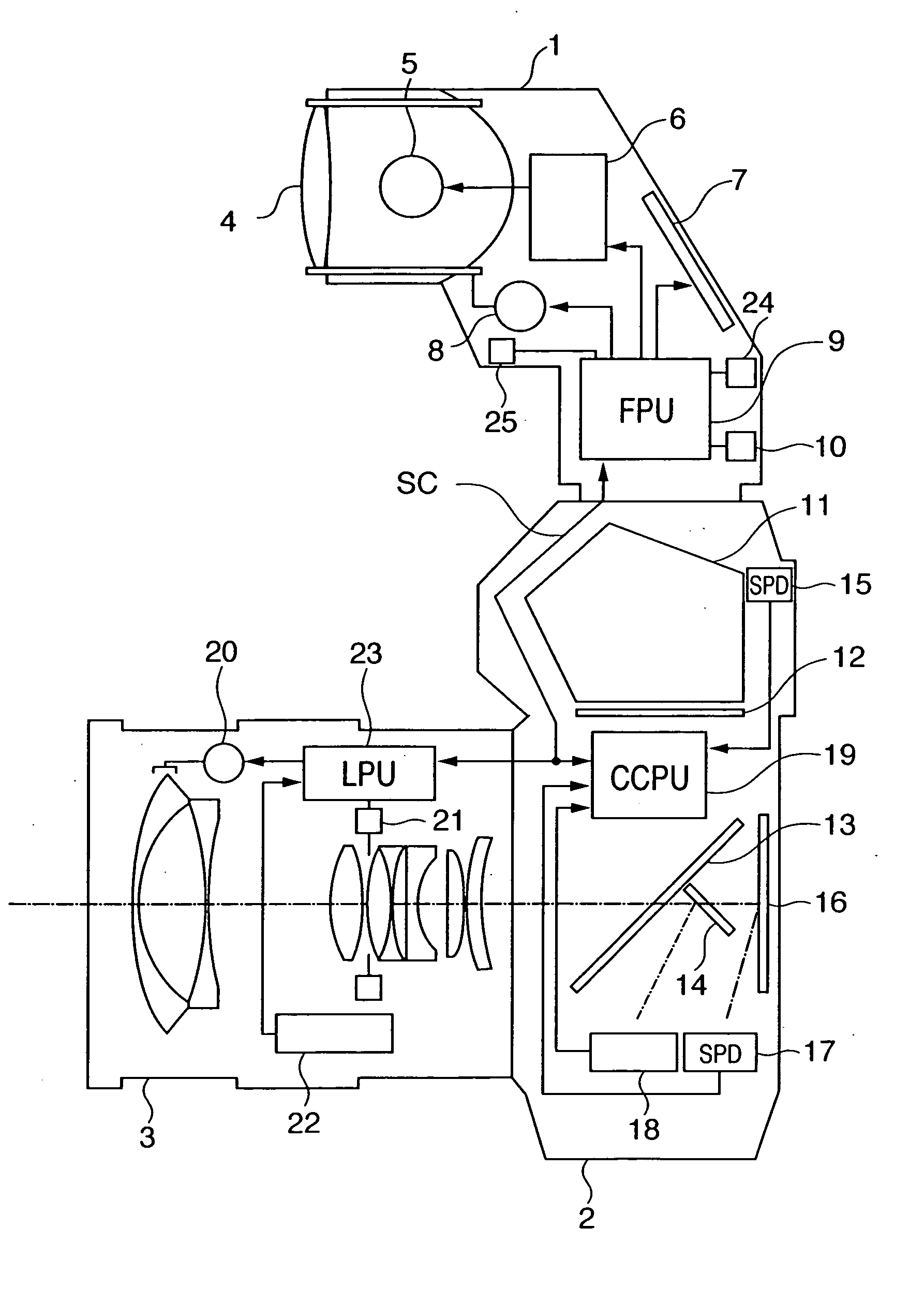
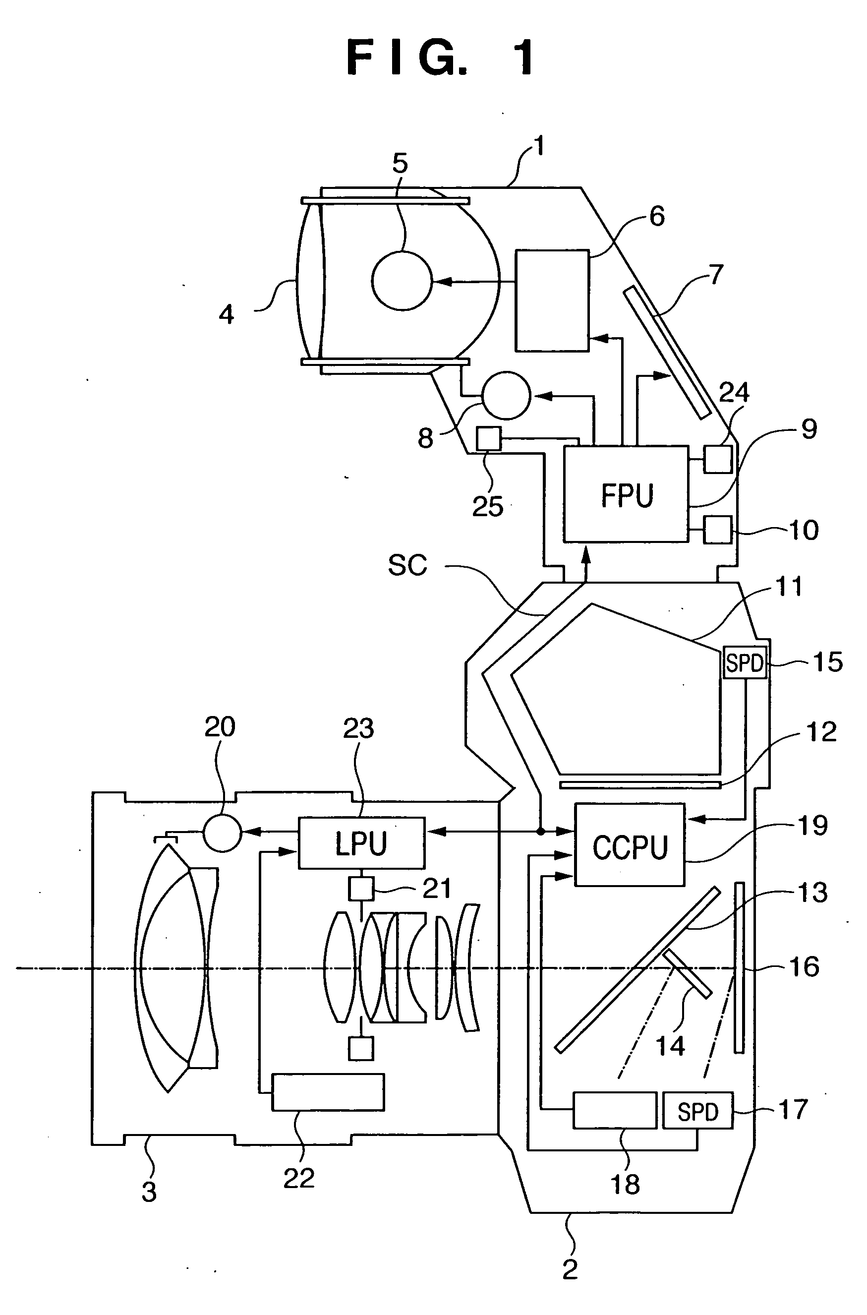
[0016] The present invention has been made in consideration of the above situation, and has as its object to provide a stroboscopic device and camera system capable of always adjusting the irradiation angle of irradiating light to an optimum value, and also capable of accurately displaying set information of a camera.

Problems solved by technology

Therefore, when a stroboscopic device is attachable to cameras different in frame size, the irradiation angle cannot be set to an optimum value on the basis of only focal length information of a lens.
However, if the number of variable steps of the strobe irradiation angle increases, the process of conversion from the focal length and image size into the light distribution angle performed by arithmetic processing in the stroboscopic device is complicated.
However, since the movement and light distribution angle of the strobe light-emitting portion are changed in accordance with the width and moving velocity of the shutter slit so that the stroboscopic device which emits light in synchronism with the start of exposure of the focal-plane shutter irradiates only the region of an object to be photographed in the region of the slit width, the mechanism is complicated, and the tracking control of synchronous communication when the shutter speed is high is a problem.
Unfortunately, if the master strobe is detached from the camera and used as a slave strobe, the last-set irradiation angle sometimes remains because the last settings cannot be canceled.

Method used


Image

  • Camera system, stroboscopic device, methods of controlling the camera system and stroboscopic device, program, and storage medium
  • Camera system, stroboscopic device, methods of controlling the camera system and stroboscopic device, program, and storage medium
  • Camera system, stroboscopic device, methods of controlling the camera system and stroboscopic device, program, and storage medium

Examples


first embodiment

[0084] The operation of the FPU 9 of the first embodiment will be described below with reference to a flowchart shown in FIG. 5A.

[0085] When the power switch (not shown) is turned on to make the FPU 9 operable, the FPU 9 starts a predetermined operation from step S101. [0086] [Step S101] The FPU 9 initializes its own memory and ports. As will be described later, as the aperture size information (magnification information) and the focal length information of the lens to be acquired from the CCPU 19 and stored in its own memory, the FPU 9 stores default values, e.g., ×1 of the 135 size as the aperture size information, and 50 mm as the focal length information of the lens. [0087] [Step S102] The FPU 9 prepares for light emission by allowing the boosting circuit 6 to start operating. [0088] [Step S103 (information input unit / step)] The FPU 9 checks whether the focal length information of the photographing lens is acquired from the CCPU 19 via the communication line SC. If the focal le...

second embodiment

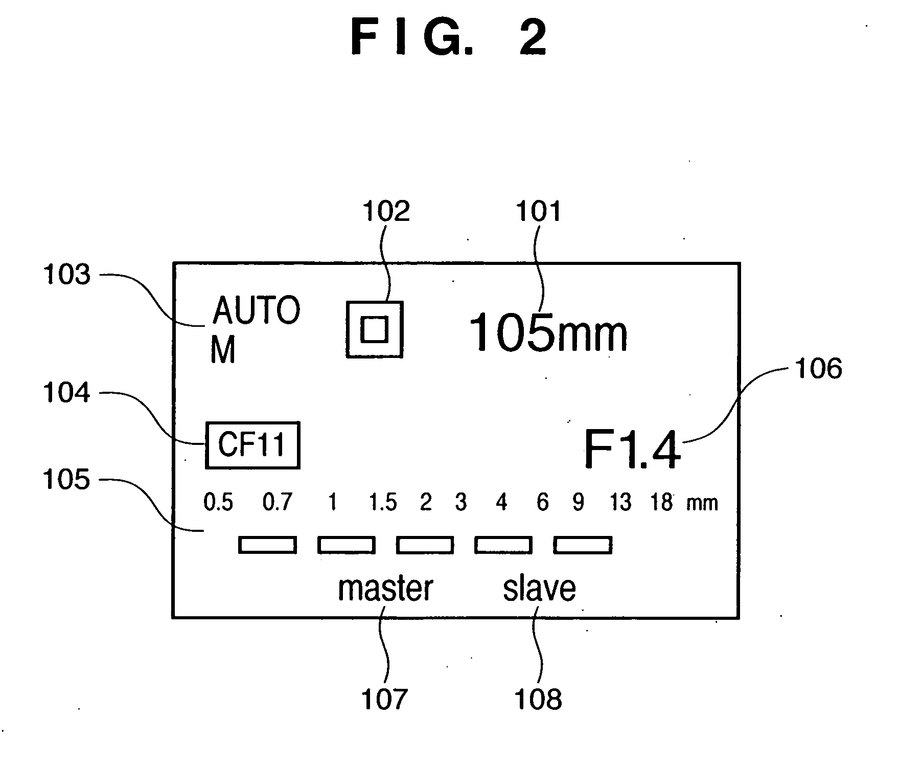
[0116] In the second embodiment explained below, a photographer can select, by a custom function (CF), a first mode in which the irradiation angle of irradiating light of strobe light is controlled on the basis of the photographing lens focal length information and aperture size information acquired from the camera, and a second mode in which the irradiation angle of strobe light is controlled on the basis of only the focal length information.

[0117] The same reference numerals as in the flowchart of FIG. 5A denote steps having the same operations in FIG. 5B, and an explanation thereof will be omitted.

[0118]FIG. 5B differs from the flowchart shown in FIG. 5A in that step S119 is added between steps S106 and S107. [0119] [Step S106] The FPU 9 checks whether the aperture size information (magnification information) of the camera is transmitted from the CCPU 19 via the communication line SC. If the aperture size information (magnification information) of the camera is transmitted, the...

third embodiment

[0129] In the third embodiment described below, it is possible to select a normal mode in which the irradiation angle of strobe light is set to an optimum value on the basis of the photographing lens focal length information and camera aperture size information input from the camera, and a slave mode in which light emission is controlled on the basis of a command from the master strobe. In the slave mode, the strobe light is set at a predetermined irradiation angle by inhibiting the normal mode.

[0130] The same reference numerals as in the flowchart of FIG. 5A denote steps having the same operations in FIG. 6A, and an explanation thereof will be omitted.

[0131]FIG. 6A differs from FIG. 5A in that steps S120 and S121 are added. [0132] [Step S120 (control unit / step)] The FPU 9 determines whether the switch WSLSW shown in FIG. 7 is turned on to set the wireless slave mode. In the normal mode in which the switch WSLSW is OFF, the flow advances to step S107. In the wireless slave mode in...


PUM


Abstract

A camera system includes a stroboscopic device (1) and camera (2). The camera (2) includes an information output unit which outputs, to the stroboscopic device (1), focal length information of a photographing lens, and size information indicating a magnification with respect to a reference size of an exposure surface of an image sensing element. The stroboscopic device (1) includes an irradiation angle changing unit (8) which changes the irradiation angle of strobe light, an information input unit (9) which receives the focal length information and size information from the camera (2), and a control unit (9) which sets the irradiation angle at a wide angle, if the product of the focal length and magnification is in the middle of a reference focal length range.

Description

FIELD OF THE INVENTION [0001] The present invention relates to a stroboscopic device attached to (incorporated in) a camera and having a function of changing the irradiation angle of irradiating light, and a camera system. BACKGROUND OF THE INVENTION [0002] As a conventional stroboscopic device, a zoom strobe capable of changing the irradiation angle in accordance with the focal length of a lens, i.e., the photographing angle of view has been put into practical use. In addition, a zoom strobe by which a camera outputs focal length information of an attached lens to a stroboscopic device, and, on the basis of this information, the stroboscopic device automatically changes and sets the irradiation angle to an optimum value has been put into practical use. [0003] When the irradiation angle is to be automatically set to an optimum value on the basis of focal length information of a lens, it can be unconditionally done if the aperture size of a camera to which this stroboscopic device is...

Claims


Application Information

Patent Timeline
IPC IPC(8): G03B7/16G03B15/02G03B15/05H04N5/222
CPCG03B15/05G03B7/16G03B2215/0557G03B2215/0585
Inventor ICHIHARA, YOSHIRO
Owner CANON KK
Learn More