Low profile mixing plant for particulate materials

a technology of mixing plant and particulate material, which is applied in the direction of cement mixing apparatus, mixing methods, and ingredients storage, etc., can solve the problems of exposing the silo to greater earthquake loads, introducing significant structural complexities, and placing further structural requirements

Inactive Publication Date: 2005-10-06
WALLGREN KRIS
View PDF25 Cites 46 Cited by
  • Summary
  • Abstract
  • Description
  • Claims
  • Application Information

AI Technical Summary

Benefits of technology

[0019] The first storage receptacle may include a first discharge control apparatus associated with the first discharge port for controlling discharge of the first component onto the first conveyor; and the second storage receptacle may include a second discharge control apparatus associated with the second discharge port for controlling discharge of the second component onto the second conveyor.
[0020] The first and second discharge control apparatuses may each be associated with at least one load cell for measuring a quantity of the respective first and second component before their discharge onto the respective first and second conveyors.
[0021] The first storage receptacle may comprise a first platform positioned near the first discharge control apparatus for supporting a plant operator, the second storage receptacle may comprise a second platform positioned near the second hopper for supporting the plant operator, and the first and second platforms may be substantially co-planar and connected along one adjacent edge.
[0022] The first and second storage receptacles may be positioned over the respective first and second conveyors at a discharge height adjacent to the ground level of the plant. The discharge height may be approximately no more than 8 feet from ground level.

Problems solved by technology

While such a stacked arrangement that has the silos mounted over the gantry facilitates the discharge of materials, it also introduces significant structural complexities.
The elevation of each silo on the gantry produces significant bending loads upon the gantry which places further structural requirements upon the gantry and its foundations.
Further, the elevation of a silo tends to expose the silo to greater earthquake loads.
However, conventional belt conveyors are typically not suitable for transporting very fine materials such as cementitious powder, since such conveyors cannot effectively impart the motion of the belt to the powder material being transported, and hence the transport of the material along the belt cannot be effectively controlled.
Due to the very fine nature of cement powder, unenclosed belt transport is also typically not used because even very gentle winds may remove some cement powder from the belt, and hence even with a controlled discharge from the silo onto the input end of the belt, it is difficult to predict the amount of cement powder that will be discharged from the output end of the belt conveyor.
However, due to the very high power required to operate a screw-type conveyor, the length of such a conveyor is typically limited to approximately thirty feet, and the incline to which the conveyor may operate in this type of installation is typically limited to approximately forty-five degrees.
As such, the elevation of the cement powder silo in this type of installation remains subject to significant bending loads that imposes significant structural requirements upon the support structure of the silo and its foundations.

Method used


Image

  • Low profile mixing plant for particulate materials
  • Low profile mixing plant for particulate materials
  • Low profile mixing plant for particulate materials

Examples


Embodiment Construction

[0036] The description which follows, and the embodiments described therein, are provided by way of illustration of an example, or examples, of particular embodiments of the principles of the present invention. These examples are provided for the purposes of explanation, and not limitation, of those principles and of the invention. In the description, which follows, like parts are marked throughout the specification and the drawings with the same respective reference numerals.

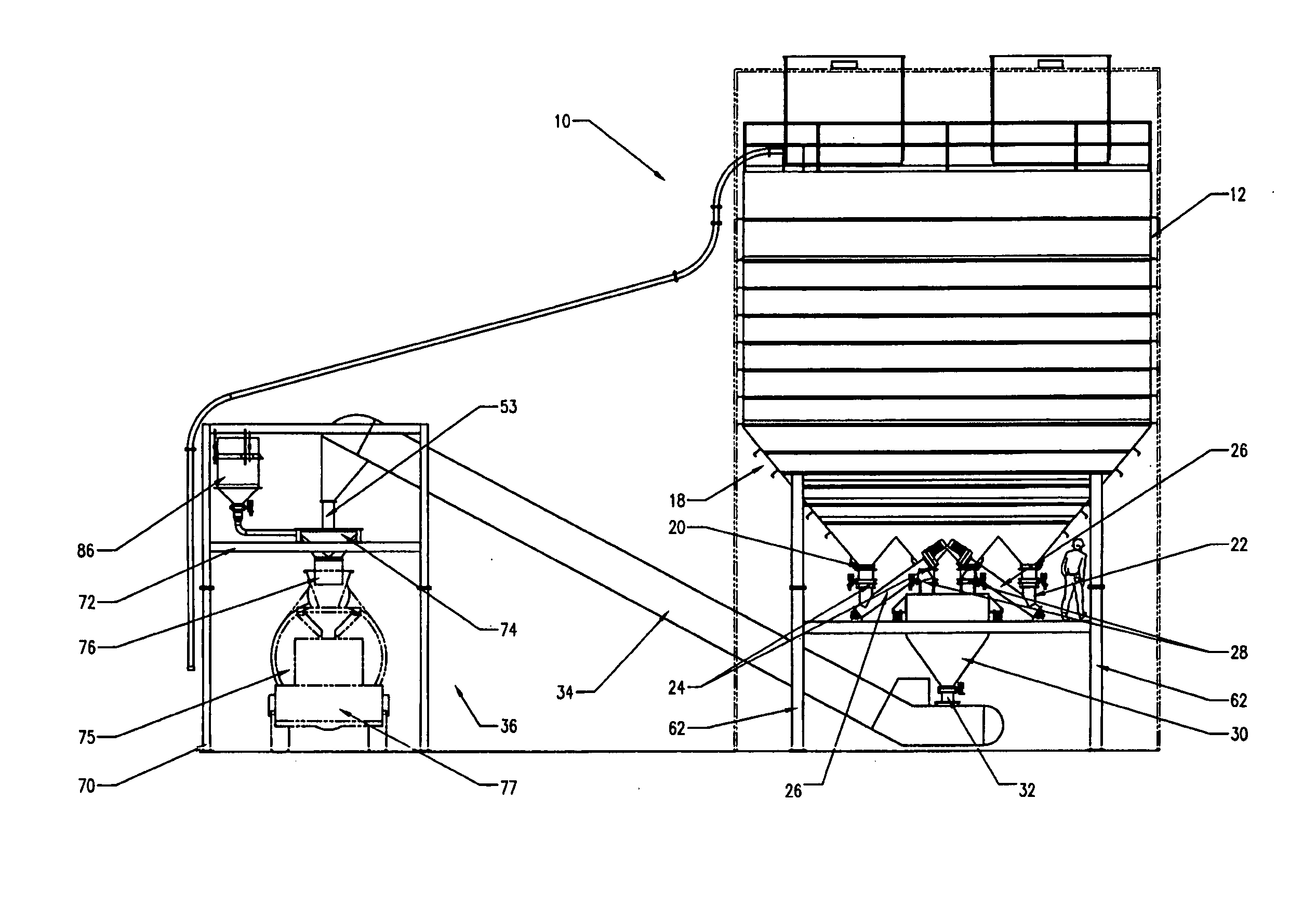
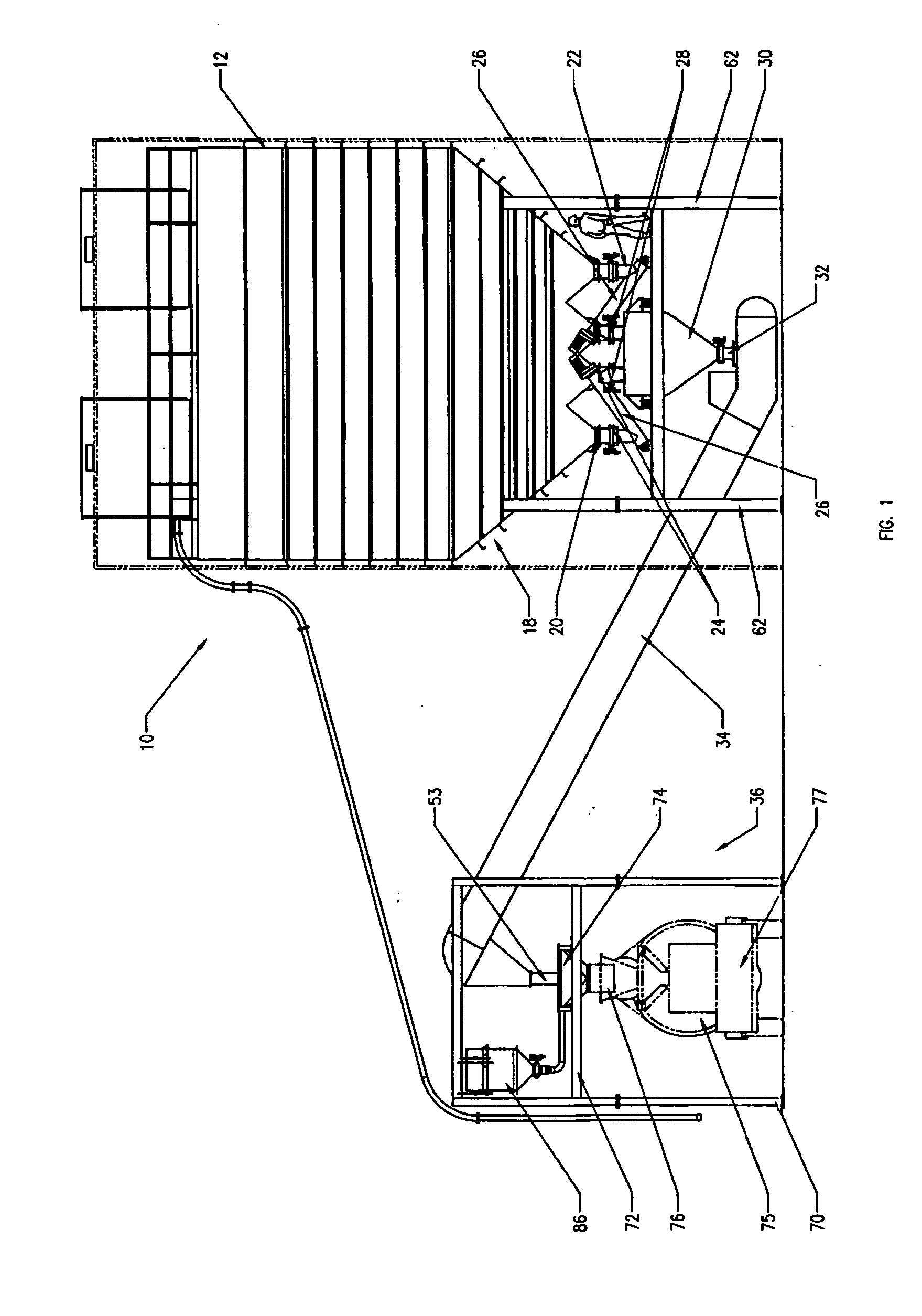
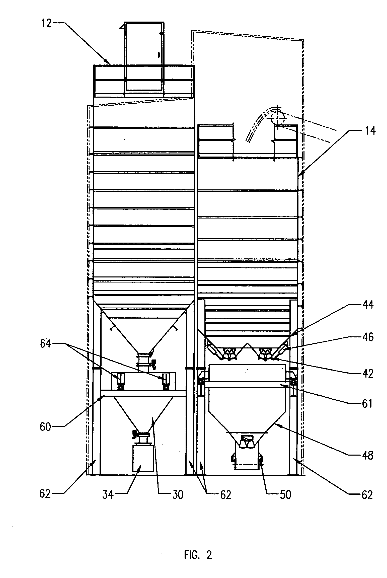
[0037] Referring to FIGS. 1 through 4, in one embodiment a plant generally indicated 10 has a pair of storage receptacles such as silos 12, 14 and a mixing station such as gantry 36 spaced apart from the silos 12, 14. The silos 12, 14 may be mounted upon a support structure, such as legs 62, to a foundation (not shown) in the ground of plant 10. The silos 12, 14 may be placed in a side by side along a foundation (not shown) of a plant and structurally connected to one another to form an integral unit. This may...


PUM

PropertyMeasurementUnit
discharge heightaaaaaaaaaa
lengthaaaaaaaaaa

Abstract

A low profile particulate mixing plant is described. The plant is suitable for discharging the components of a particulate mixture. The plant includes a pair of storage receptacles located side-by-side. Each of the receptacles has a discharge adjacent an underside thereof to transfer a component of the particulate material mix within each receptacle to a respective conveyor at a height adjacent to ground level. The conveyor elevates the components from the discharges to a mixing station spaced from the receptacles. The plant is suitable for use as a concrete mixing plant.

Description

[0001] This application claims the benefit of U.S. Provisional Application No. 60 / 543,273, filed Feb. 11, 2004.FIELD OF THE INVENTION [0002] The present invention relates generally to mixing plants for particulate materials, and more specifically, the present invention is adaptable to concrete mixing plants. BACKGROUND OF THE INVENTION [0003] It is conventional to deliver concrete to a construction site on a vehicle equipped with a mixing drum. The concrete is thus delivered as a fully mixed slurry and can be dispatched directly to the ultimate location in which it is to be used. The mixing vessels are charged with the materials from which the concrete is mixed at a batch plant. Typically the batch plant includes silos for the aggregate and the cement powder which are discharged in the required ratios from the undersides of the silos into the mixing vessel of the vehicle for mixing with water to make concrete slurry. [0004] In prior art installations, the silos are mounted on a gant...

Claims


Application Information

Patent Timeline
Patent Type & Authority Applications(United States)
IPC IPC(8): B01F3/18B28C5/08B28C7/00B28C7/04B28C7/06E04H7/22
CPCB28C5/0818B28C7/0076B28C7/062B28C7/0481B28C7/0436
Inventor WALLGREN, KRIS
Owner WALLGREN KRIS
Why Eureka
Try Eureka