
Honeycomb structure and method for production of said structure

a honeycomb and structure technology, applied in the field of alveolar structures, can solve the problems of drop in electrical conductivity within the assembly, persisting corrosion problems, and disadvantages of using such devices

Inactive Publication Date: 2005-10-06
COMMISSARIAT A LENERGIE ATOMIQUE ET AUX ENERGIES ALTERNATIVES
View PDF17 Cites 22 Cited by
  • Summary
  • Abstract
  • Description
  • Claims
  • Application Information

AI Technical Summary

Benefits of technology

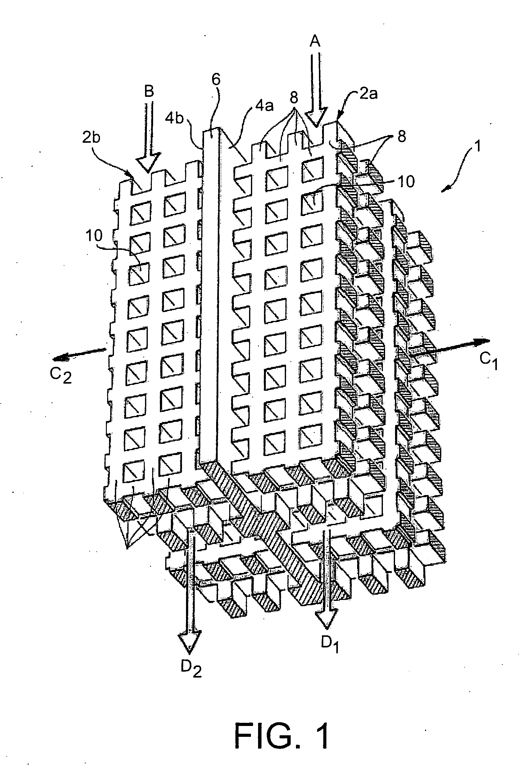
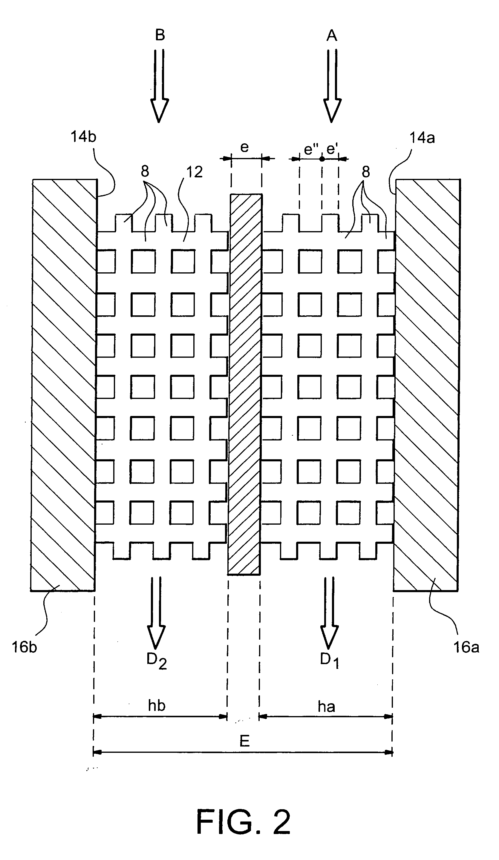
[0035] The further aim of the invention is to propose an alveolar structure of simple design, and for which it is possible to perfectly control the internal geometry of its different alveolar zones.
[0038] Advantageously, the invention proposes an alveolar structure of simple design in which the internal geometry of the alveolar zones is easily adaptable, depending on the encountered needs.
[0048] Furthermore, the metallic layers comprise at least one binder such as bronze. This advantageously makes it possible to obtain alloys for which a sintering operation can be carried out at low temperature.

Problems solved by technology

However, it has been observed that this specific arrangement of means would not enable a sufficiently large exchange surface to be obtained to lead to an acceptable yield of electrochemical conversion with a view to an industrial application.
However, the fact of adding a metallic foam at the level of the bipolar plate contributes to creating a considerable resistance, which leads to a drop in the electrical conductivity within the assembly.
Even if the problem relating to the electrical conduction may be partially resolved by compressing the metallic foam, it turns out that, whatever the case, problems of corrosion persist, notably due to the presence of numerous defects such as strand ruptures within the metallic foam.
On the other hand, other disadvantages remain in the use of such devices.
Indeed, by using metallic foams as distribution zones for reagents and the evacuation of different products, one cannot correctly control the periodicity of the metallic foam type structure.
Furthermore, an additional disadvantage resides in the impossibility of controlling, in an easy manner, the internal geometry of the alveolar structure, this being reflected by the incapacity to vary the geometry of the distribution zone in the desired manner.

Method used


Image

  • Honeycomb structure and method for production of said structure
  • Honeycomb structure and method for production of said structure
  • Honeycomb structure and method for production of said structure

Examples


Embodiment Construction

[0034] The aim of the present invention is therefore to overcome all or part of the disadvantages of alveolar structures of the prior art.

[0035] The further aim of the invention is to propose an alveolar structure of simple design, and for which it is possible to perfectly control the internal geometry of its different alveolar zones.

[0036] A yet further aim of the present invention is a method of manufacturing an alveolar structure such as that fulfilling the aim of the invention mentioned above.

[0037] To do this, a first aim of the invention is an alveolar structure comprising at least one alveolar zone partially delimited by an associated leak tight surface. According to the invention, each alveolar zone is formed of a plurality of metallic layers superimposed parallel to the associated leak tight surface, each metallic layer comprising a network of passages opening out on either side of said metallic layer.

[0038] Advantageously, the invention proposes an alveolar structure o...


PUM

PropertyMeasurementUnit
Structureaaaaaaaaaa
Metallic bondaaaaaaaaaa

Abstract

An alveolar structure and a method of manufacturing an alveolar structure. The alveolar structure includes at least one alveolar zone partially delimited by an associated leak tight surface. Each alveolar zone is formed of a plurality of metallic layers superimposed parallel to the associated leak tight surface, each metallic layer including a network of passages opening out on either side of the each metallic layer. The alveolar structure may find particular application to fuel cells and heat exchangers.

Description

TECHNICAL FIELD [0001] The technical field of the present invention concerns that of the production of energy requiring a high compactness of the components used. More specifically, the invention relates to alveolar structures used in this specific technical field. [0002] The alveolar structures find application, in particular, in the field of fuel cells and, more specifically, in that of fuel cells comprising a membrane as electrolyte as well as bipolar plates, said plates being composed of alveolar structures. [0003] Furthermore, the invention is also applicable to the field of heat exchangers using alveolar structures. [0004] Finally, the present invention further concerns methods for manufacturing said alveolar structures. STATE OF THE PRIOR ART [0005] In this field, fuel cells using alveolar structures are known. [0006] Indeed, a fuel cell is an assembly generally comprising a plurality of elementary cells stacked one against the other. In each of the elementary cells of the fu...

Claims


Application Information

Patent Timeline
IPC IPC(8): H01M8/02B32B3/10
CPCF28F13/003H01M8/0206H01M8/0247H01M8/0258Y02P70/56B22F3/1055Y10T428/12361B33Y70/00H01M8/0271H01M8/0267Y02P10/295Y10T428/12479B22F3/1103Y02P10/25Y02P70/50Y02E60/50B22F10/28
Inventor REVOL, STEPHANE
Owner COMMISSARIAT A LENERGIE ATOMIQUE ET AUX ENERGIES ALTERNATIVES
Learn More