System and method for capacity control in a multiple compressor chiller system

a chiller system and multiple compressor technology, applied in the direction of positive displacement liquid engines, lighting and heating apparatus, domestic cooling apparatus, etc., can solve the problems of reducing the efficiency of the redundant compressor, reducing the efficiency of the system, and reducing the cycle of the compressor. , the effect of improving the system efficiency

Active Publication Date: 2005-10-13
JOHNSON CONTROLS TYCO IP HLDG LLP
View PDF50 Cites 39 Cited by
  • Summary
  • Abstract
  • Description
  • Claims
  • Application Information

AI Technical Summary

Benefits of technology

The present invention has two main benefits: it reduces compressor cycling (the process where air is compressed repeatedly) and improves system efficiency by running multiple compressors at once to meet demand. These improvements lead to better performance and cost savings for users.

Problems solved by technology

The technical problem addressed in this patent is how to effectively control the capacity of a multi-compressor chiller system without incurring high costs or causing failures due to individual motor malfunctions.

Method used


Image

  • System and method for capacity control in a multiple compressor chiller system
  • System and method for capacity control in a multiple compressor chiller system
  • System and method for capacity control in a multiple compressor chiller system

Examples


Embodiment Construction

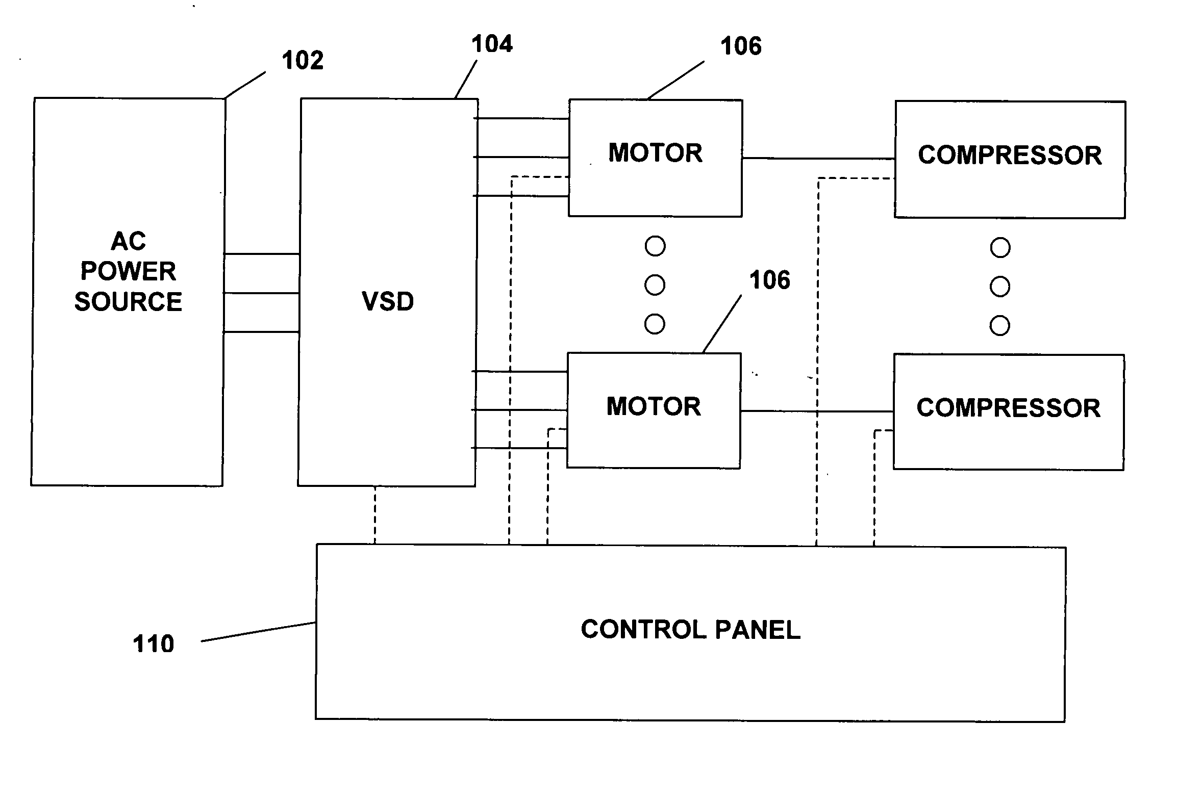
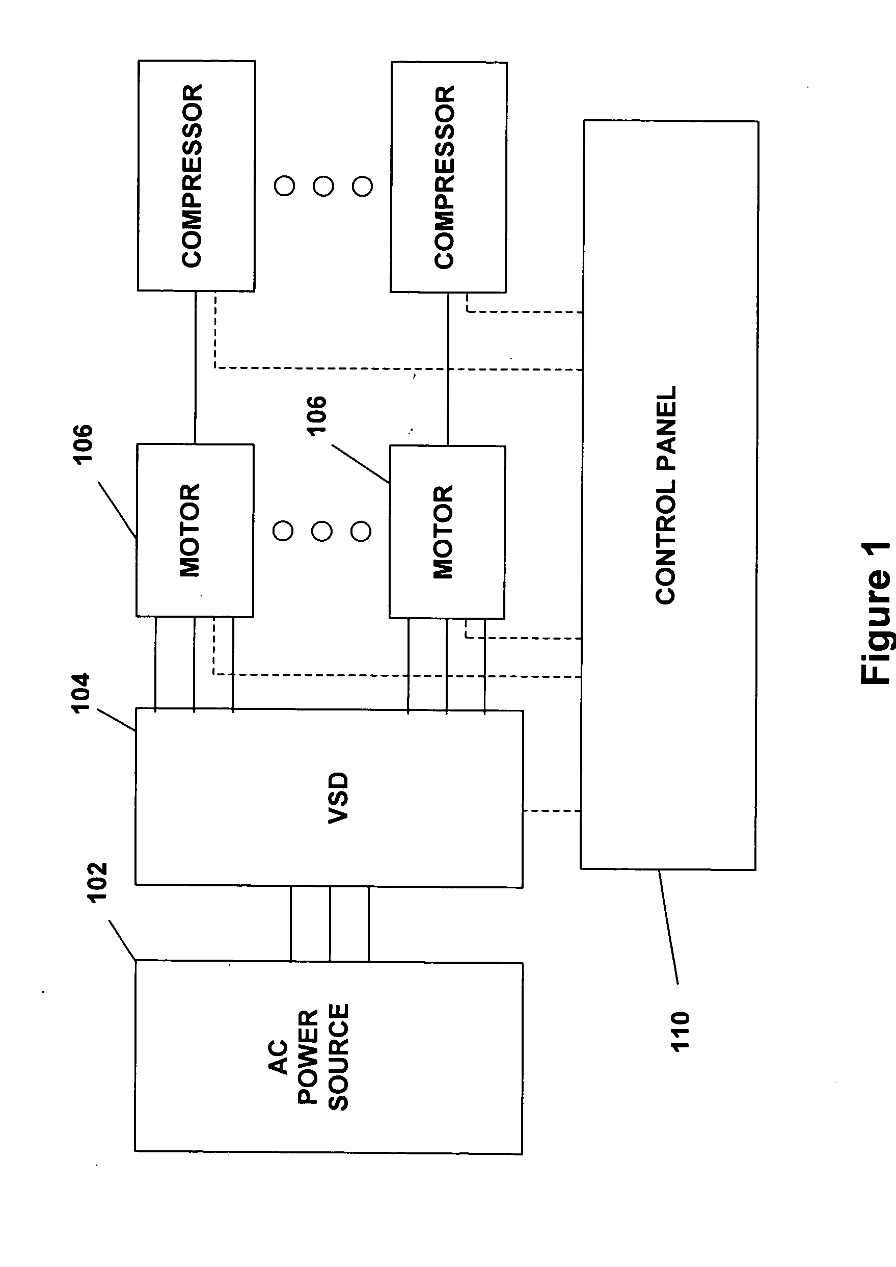
[0022]FIG. 1 illustrates generally an application that can be used with the present invention. An AC power source 102 supplies a variable speed drive (VSD) 104, which powers a plurality of motors 106. The motors 106 are preferably used to drive corresponding compressors that can be used in a refrigeration or chiller system. A control panel 110 can be used to control operation of the VSD 104 and can monitor and / or control operation of the motors 106 and compressors.

[0023] The AC power source 102 provides single phase or multi-phase (e.g., three phase), fixed voltage, and fixed frequency AC power to the VSD 104 from an AC power grid or distribution system that is present at a site. The AC power source 102 preferably can supply an AC voltage or line voltage of 200 V, 230 V, 380 V, 460 V, or 600 V at a line frequency of 50 Hz or 60 Hz, to the VSD 104 depending on the corresponding AC power grid.

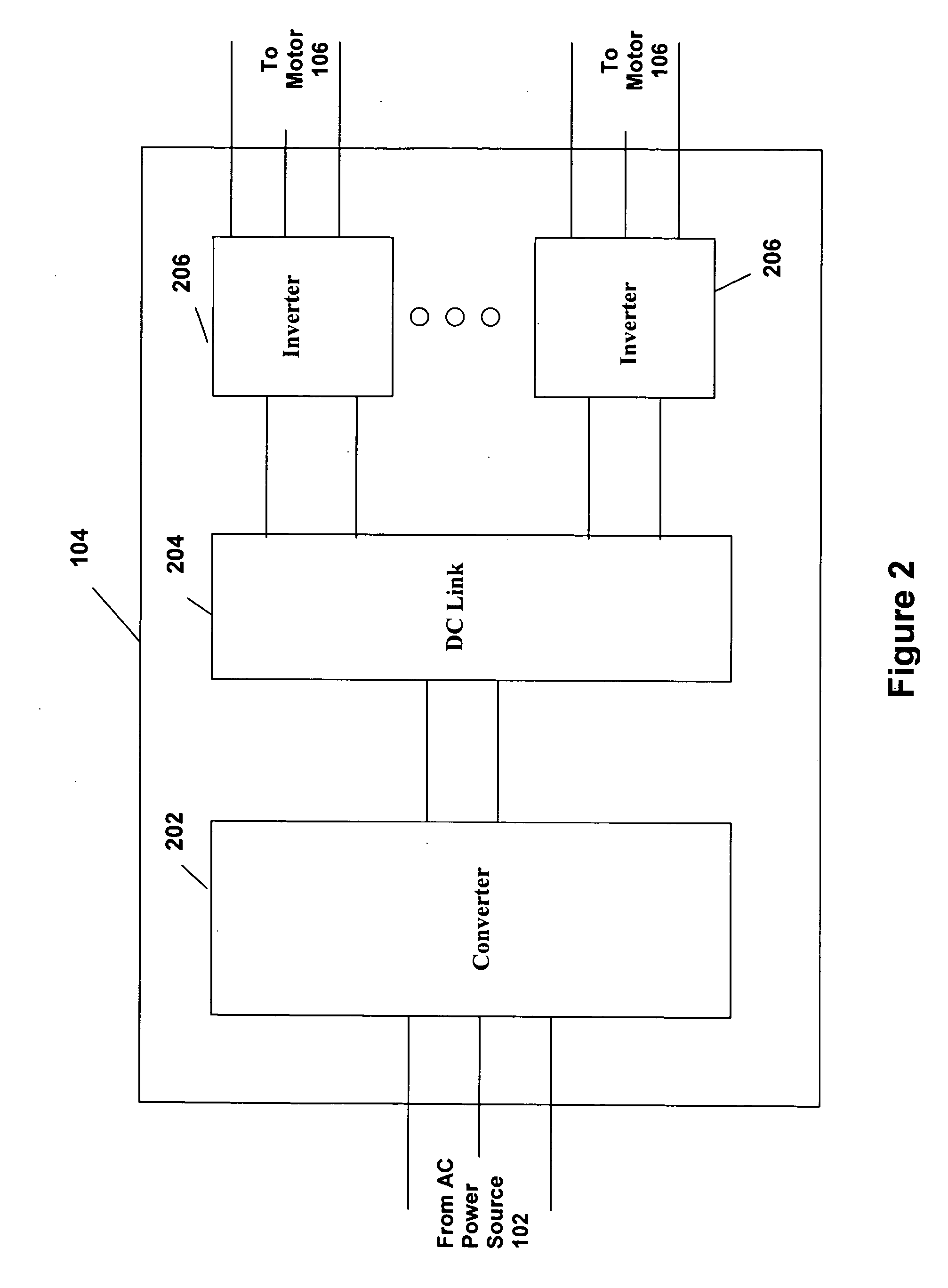
[0024] The VSD 104 receives AC power having a particular fixed line voltage and fixed line ...


PUM


Abstract

A capacity control algorithm for a multiple compressor liquid chiller system is provided wherein the speed and number of compressors in operation are controlled in order to obtain a leaving liquid temperature setpoint. In response to an increase in the load in the chiller system, the algorithm determines if a compressor should be started and adjusts the operating speed of all operating compressors when an additional compressor is started. In response to a decrease in the load in the chiller system with multiple compressors operating, the algorithm determines if a compressor should be de-energized and adjusts the operating speed of all remaining operating compressors when a compressor is de-energized.

Description


Claims


Application Information

Patent Timeline
Owner JOHNSON CONTROLS TYCO IP HLDG LLP
Why Eureka
Try Eureka