Modified manual control lever devices and methods

a technology of manual control levers and control levers, which is applied in the direction of mechanical control devices, cycle equipment, instruments, etc., can solve the problems of difficult engagement of the user's hand or digits with the accessible surface area of the control lever, and the difficulty of addressing the problem of lever access from a variety of user hand positions and/or angles, so as to improve the accessibility of the control lever. , the effect of improving the accessibility of the control lever

Inactive Publication Date: 2005-10-13
CRABTREE RICHARD W
View PDF14 Cites 4 Cited by
  • Summary
  • Abstract
  • Description
  • Claims
  • Application Information

AI Technical Summary

Benefits of technology

[0005] This invention provides devices and methods for improving accessibility of vehicle control levers (such as throttle levers and the like) utilized on motor vehicles having handlebar-type steering assemblies including handle grips (such as snowmobiles, for example), to accommodate different riding conditions encountered and riding styles utilized by operators of such vehicles. Such control levers typically have a distal end and are movable toward and away from the handle grip in a plane defined between the handle grip and the throttle lever. The devices are adapted to improve control lever access from a variety of different user hand positions and / or angles resulting from different user body positions relative to the lever. The devices of this invention are simple to apply and utilize, are inexpensive to implement, require little original equipment modification or rider retraining, and leave the handle grip area uncluttered.

Problems solved by technology

However, different riding conditions encountered and riding styles utilized by operators on such vehicles require, in many cases, frequent and repeated shifting of body position relative to the vehicle during operation, including, for example, standing (on pegs, platforms or the like), sitting, and leaning laterally, forward and / or back.
These movements make engagement of the user's hand or digits with the accessible surface area of the control levers difficult in positions other than the defined body position.
Such heretofore known extenders have addressed lever lengthening (see U.S. Pat. No. 6,494,113) or wind / cold shielding (see U.S. Pat. No. 4,838,113), but have not addressed adequately the problem of lever access from a variety of user hand positions and / or angles.
Modified throttle assemblies allowing throttle lever position change, multi-directional operability or the like have been heretofore suggested and or utilized (see U.S. Patent Application Publication Nos. U.S. 2002 / 0026849 A1 and U.S. 2001 / 0045141 A1), but are unduly complex (and therefore expensive to implement) and / or require extensive equipment modification, rider retraining or the like.
The addition of more control levers on handlebar-type steering assemblies, however, unduly complicates the use of vehicle control mechanisms and crowds the handle grip area.

Method used


Image

  • Modified manual control lever devices and methods
  • Modified manual control lever devices and methods
  • Modified manual control lever devices and methods

Examples


first embodiment

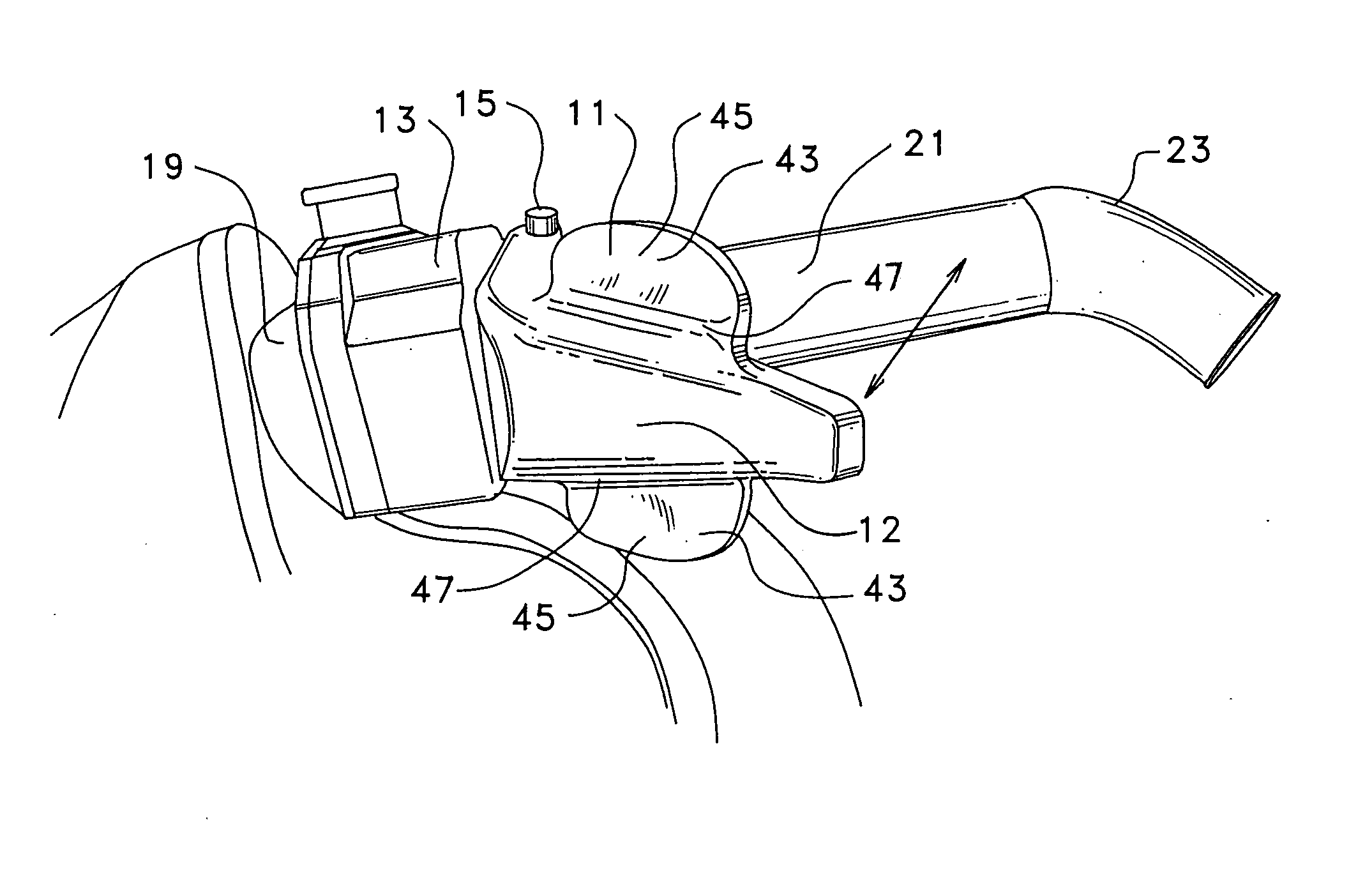
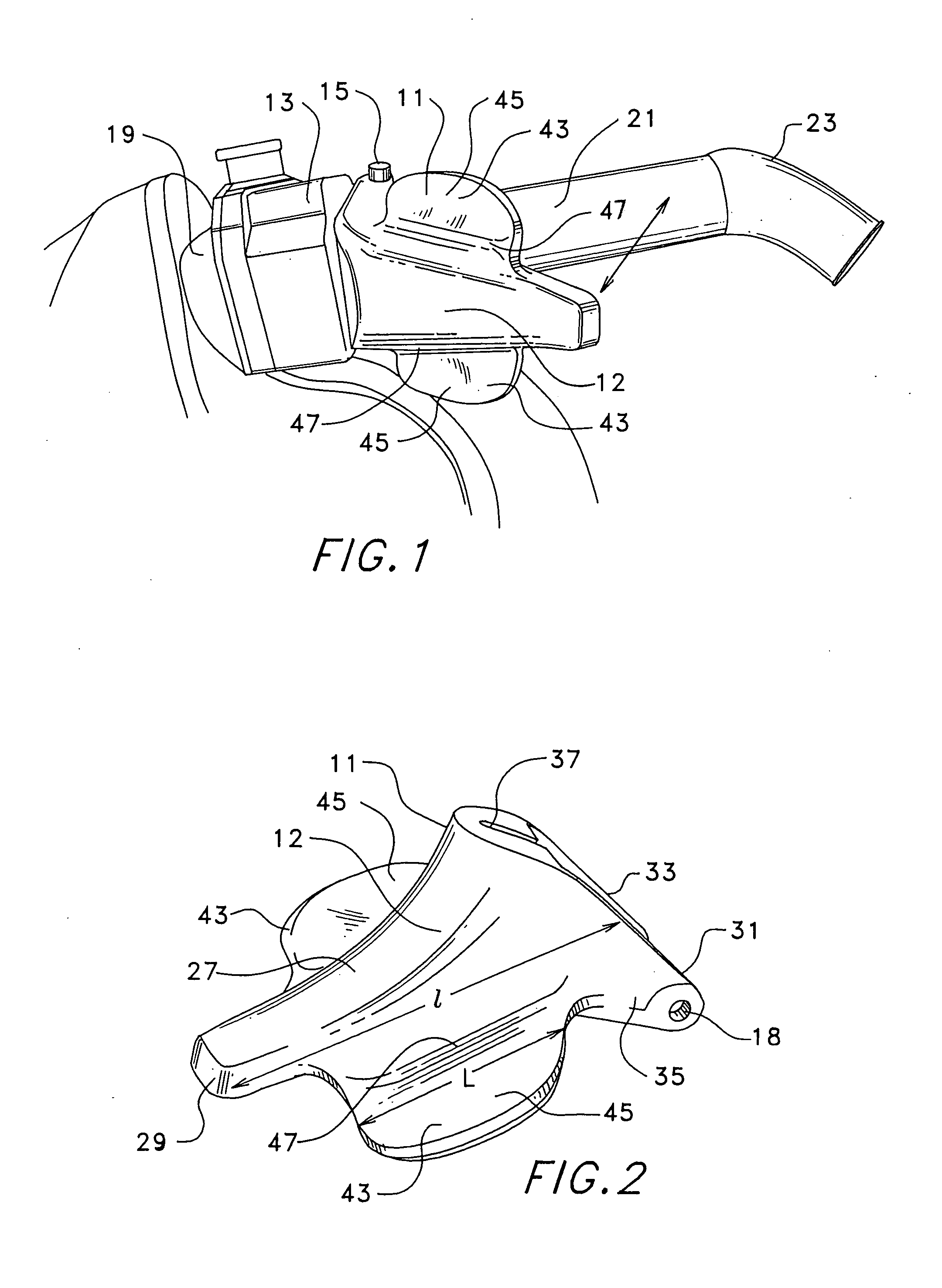
[0026]FIGS. 1 and 2 show the device of this invention for original equipment manufacture or for use as a replacement part. Modified form control lever 11 of this invention includes a main body 12 pivotably mounted at snowmobile control lever body structure 13 by a pivot pin assembly (including pin 15 and retainer 17, for example, as shown in FIG. 4 and as is known for use with such throttle levers) through pivot connections (openings 18). Lever 11 is manually pivotable to operate, for example, a throttle cable-type actuator (not shown). Control lever body structure 13 is mounted on handlebar-type steering assembly 19 adjacent to handle grip 21 at one distal end 23 thereof.

[0027] Lever main body 12 is similar in many regards to known control levers having a standard configuration (as shown in FIGS. 3 and 4) except as noted herein. The standard configuration includes central portion 27 of main body 12 having a distal end 29 and a mounting end 31. The standard configuration includes co...

second embodiment

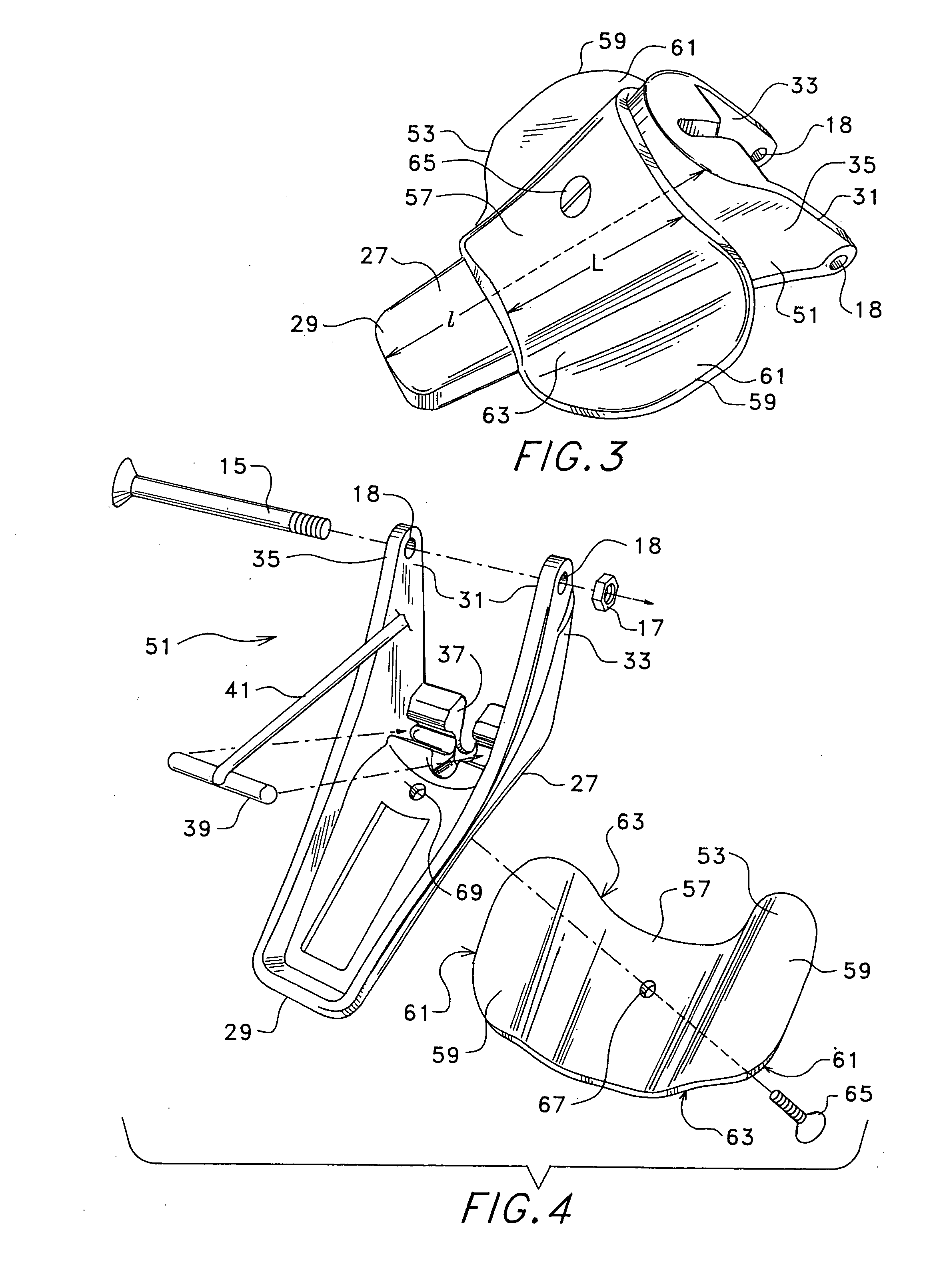
[0030] the device of this invention is shown in FIGS. 3 and 4 for application to an existing control lever 51 of standard configuration (as described above and as shown in FIGS. 3 and 4). As may be appreciated, this embodiment of the device may be mounted to control lever 51 without removal of the control lever from the vehicle. Manually accessible surface area modification attachment 53 includes main body 55 having a portion 57 contoured for mounting to the existing lever structure 51. At least one flare 59 (and, as before, preferable two flares 59) extend from portion 57 (opposite one another relative to the central portion 51 in the case of dual flares 59). Portion 57 is contoured to fit control lever 51 so that the flares extend in a direction substantially normal to the plane of lever movement (the same as shown in FIG. 1). Flares 59 provide the same enhanced surface area characteristics as discussed above with respect to lever 11 (i.e., a surface extension 61 of a size selecte...


PUM


Abstract

Modified manual control lever devices and methods for use with motorized vehicles having handlebar-type steering mechanisms including a handle grip are disclosed. The devices include a main body having at least one flare (a lateral surface extension) extending from a body portion. Two flares are preferred each extending from the body portion opposite one another. The length of the flares is selected so that a distal end of the control lever remains prominent and readily manually engageable. The flares are configured on the main body to extend, in use, in a direction substantially normal to the plane of control lever movement.

Description

FIELD OF THE INVENTION [0001] This invention relates to hand operated control levers utilized on various types of motorized vehicles having handlebar-type steering, and, more particularly, relates to control levers and lever attachments mounted adjacent to the handle grip of such vehicles. BACKGROUND OF THE INVENTION [0002] Control levers (such as brake, shifting and throttle levers, for example) are in wide use on a variety of motorized vehicles including snowmobiles, personal watercraft, all terrain vehicles, motorcycles, motorbikes, scooters and the like. Such levers are operable by engagement of an accessible surface area (manually—often by the user's thumb or fingers—causing pivoting movement thereof toward the hand grip of the handlebar-type steering common to such vehicles) to perform critical vehicle control functions during vehicle operation. [0003] Heretofore known control levers are maintained (mounted) in an orientation relative to the vehicle's hand grip(s) adequate to ...

Claims


Application Information

Patent Timeline
Patent Type & Authority Applications(United States)
IPC IPC(8): G05G1/04G05G11/00B62K23/06B62K23/02B62K11/14
CPCB62K11/14B62K23/02Y10T74/20438
Inventor CRABTREE, RICHARD W.
Owner CRABTREE RICHARD W
Why Eureka
Try Eureka