Oil-separating device

Inactive Publication Date: 2005-10-13
ROBERT BOSCH GMBH
View PDF12 Cites 46 Cited by
  • Summary
  • Abstract
  • Description
  • Claims
  • Application Information

AI Technical Summary

Problems solved by technology

The latter in particular lead to erroneous measurements when the blowby gas is conveyed through a hot film air mass meter (HFM) contained in the intake section, which results in an undesirable deterioration of the emissions behavior of

Method used


Image

  • Oil-separating device
  • Oil-separating device

Examples


Embodiment Construction

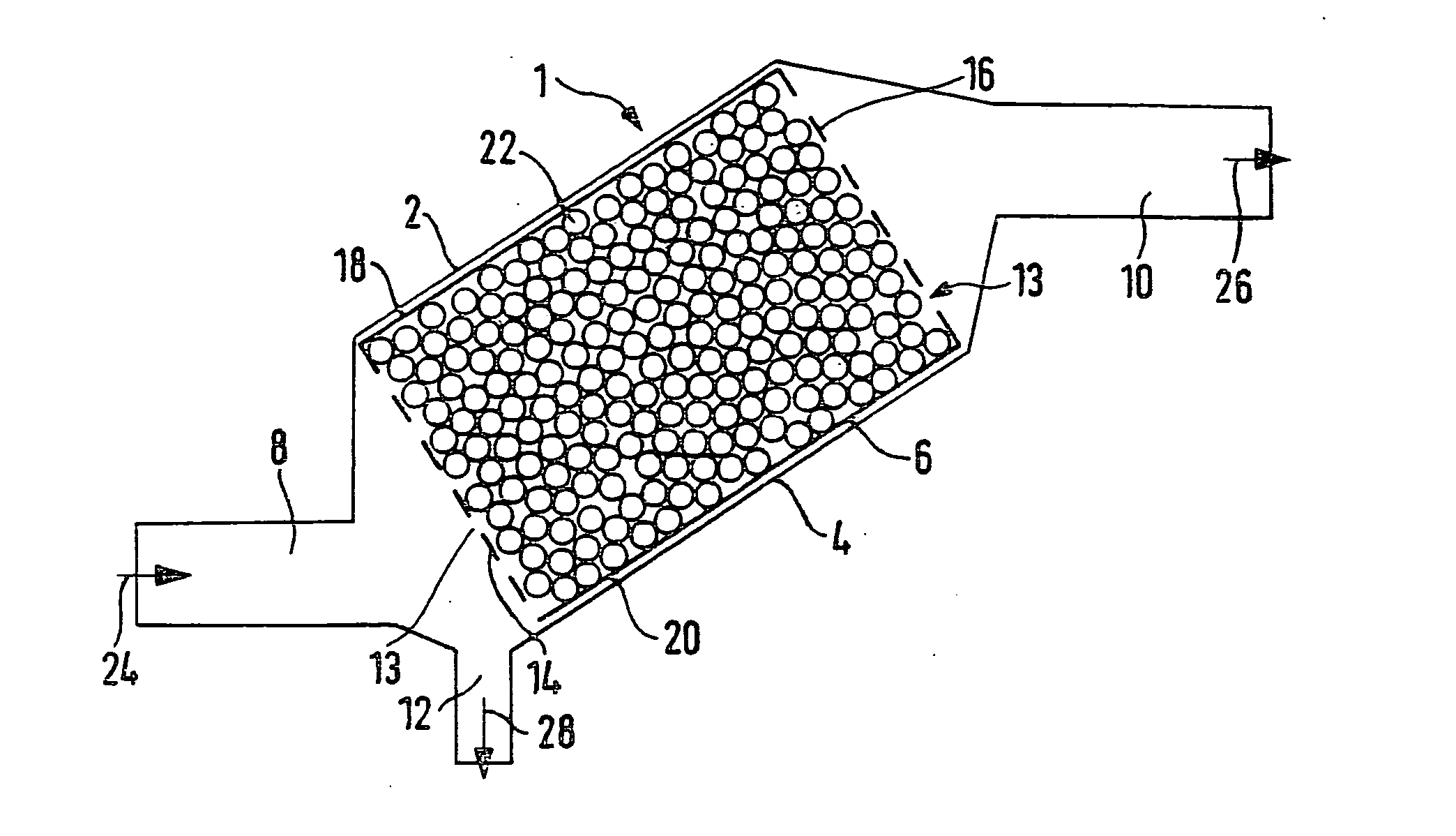
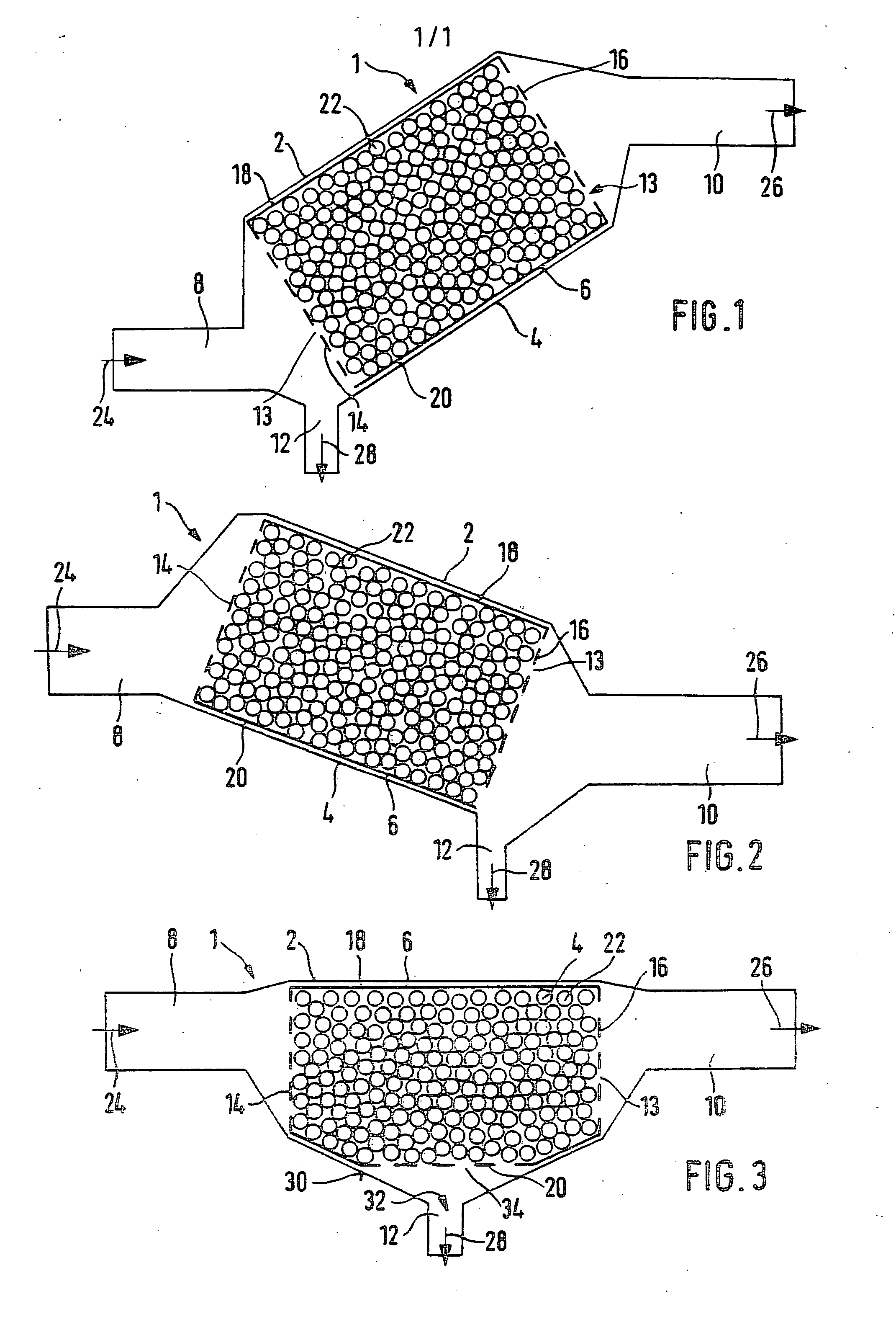
[0014]FIG. 1 shows a preferred exemplary embodiment of an oil separating device 1 according to the invention, in a schematic side view in the installed position, i.e. components that are shown at the bottom in the figure are also installed at the bottom.

[0015] The oil separating device 1 essentially includes a housing 2 and an oil separating element 6 contained in a cylindrical middle section 4 of the housing 2. This middle section of the housing 2 is embodied as a cylindrical sleeve 4, one end of which is connected to an inlet fitting 8 and the other end of which is connected to an outlet fitting 10 so that in terms of flow, the oil separating element 6 is interposed fluidically between the inlet fitting 8 and the outlet fitting 10. Vertically speaking, the outlet fitting 10 is disposed higher than the inlet fitting 8 so that the oil separating element 6 is held in the housing 2 in a position that is inclined upward in the flow direction.

[0016] The inlet fitting 8 is connected to...


PUM

PropertyMeasurementUnit
Diameteraaaaaaaaaa
Flow rateaaaaaaaaaa
Circumferenceaaaaaaaaaa

Abstract

The invention relates to an oil separating device for separating out oil droplets conveyed in a crankcase gas flow released by a crankcase ventilation of an internal combustion engine, including at least one separating element, at least part of which the gas flow passes through.
The invention provides that the separating element (6) contains a granulate (22) comprised of a plastic. This measure achieves a high separation rate of smaller oil droplets.

Description

PRIOR ART [0001] The invention is based on an oil separating device according to the preamble to claim 1, which is used to separate out oil droplets conveyed in a crankcase gas flow released by a crankcase ventilation of an internal combustion engine. [0002] In internal combustion engines, the excess pressure in a crankcase is offset by means of a crankcase ventilation; the gas sucked out by this ventilation contains high concentrations of hydrocarbons and therefore cannot be simply released into the surrounding atmosphere. Instead, this so-called blowby gas is recycled back into the intake section of the engine in order to convey it to the combustion chamber. In addition to hydrocarbons, the blowby gas also contains an oil mist with oil droplets of different droplet sizes, in particular relatively small oil droplets. The latter in particular lead to erroneous measurements when the blowby gas is conveyed through a hot film air mass meter (HFM) contained in the intake section, which ...

Claims


Application Information

Patent Timeline
IPC IPC(8): B01D46/30F01M13/04
CPCF01M13/04F01M2013/0433F01M2013/0438
Inventor ULRICH, MARKUSUHLENBROCK, DIETMAR
Owner ROBERT BOSCH GMBH
Why Eureka
Try Eureka