Shelving system

a shelving system and shelving technology, applied in the direction of display cabinets, hangers, cabinets, etc., can solve the problems of increasing the cost, affecting the efficiency of receiving, and the inability to accurately control the movement distance of the movable shelf, so as to reduce the detection error, the effect of reducing the illumination and contras

Inactive Publication Date: 2005-10-13
DAIFUKU CO LTD
View PDF6 Cites 12 Cited by
  • Summary
  • Abstract
  • Description
  • Claims
  • Application Information

AI Technical Summary

Benefits of technology

[0011] According to the above configuration, the width deviation correction control and the attitude control of the movable shelves are accurately performed, and the detecting means for performing the width deviation correction control and the attitude control of the movable shelves may only be one pair of movement detecting means, thereby reducing the cost.
[0013] The movement detecting means of the present invention includes light detecting means and adjusting means in addition to the light projecting means and the image pickup means. The illuminance of the floor is detected by the light detecting means, and when the illuminance of the floor changes, such change is detected by the light detecting means, and the detected illuminance of the floor is input to the adjusting means. The intensity of the light irradiated from the light projecting means is adjusted based on the detected illuminance of the floor by the adjusting means, and the intensity of the light received by the image pickup means is maintained constant. Therefore, the illuminance (contrast) of the fine projections or depressions of the floor detected by the image pickup means is maintained constant and the possibility of distinguishing or not distinguishing the fine projections or the depressions of the floor by the contrast is avoided, and thus the detection error is reduced.
[0014] Further, in the movement detecting means of the present invention, the light projecting means and the image pickup means are arranged so that the light irradiated diagonally from the light projecting means to the floor is reflected at approximately 90 degrees at the floor. Thus, the light reflected at the floor is most efficiently received by the image pickup means, and the difference between the light received by the image pickup means and the light not traveling towards the image pickup means due to the fine projections and depressions of the floor becomes clear, thereby improving the precision for detecting the fine projections and depressions of the floor.
[0015] In the movement detecting means, the light projecting means is arranged so that the direction of the light irradiated by the light projecting means coincides with the travel direction of the movable shelves, and the fine projections and depressions of the floor are continuously detected along the travel direction of the movable shelves. The detection of the moved distance in the travel direction thereby becomes smooth.

Problems solved by technology

In the above-mentioned conventional configuration, when the movable shelf is self-advanced, in order to achieve a shelving system capable of performing both the width-deviation correction control and the attitude control, the position reference member (magnetic tape) must be laid, and the contact-subjecting position detector (magnetic sensor) for detecting the position reference member must be provided on each movable shelf, and further, two pulse encoders must be arranged on each movable shelf to maintain the attitude of the movable shelf in the direction perpendicular to the travel path, thereby arising a problem of increase in cost.
In the movable shelf in which the position reference member is laid, and the contact-subjecting position detector as well as the pulse encoder are provided, when the movable shelf is moved in a tilted manner, the trajectory of the pulse encoder draws an arc, thereby causing an error between the moved distances of both ends and the moved distance in the travel direction, and arising a problem that an accurate attitude control of the movable shelf can not be performed.
Further, when the movable shelf is tilted, an error occurs in the moved distance in the direction at right angles to the travel path detected by the contact-subjecting detector.

Method used


Image

  • Shelving system
  • Shelving system
  • Shelving system

Examples


Embodiment Construction

[0026] The present invention will now be described in detail in conjunction with the accompanying drawings.

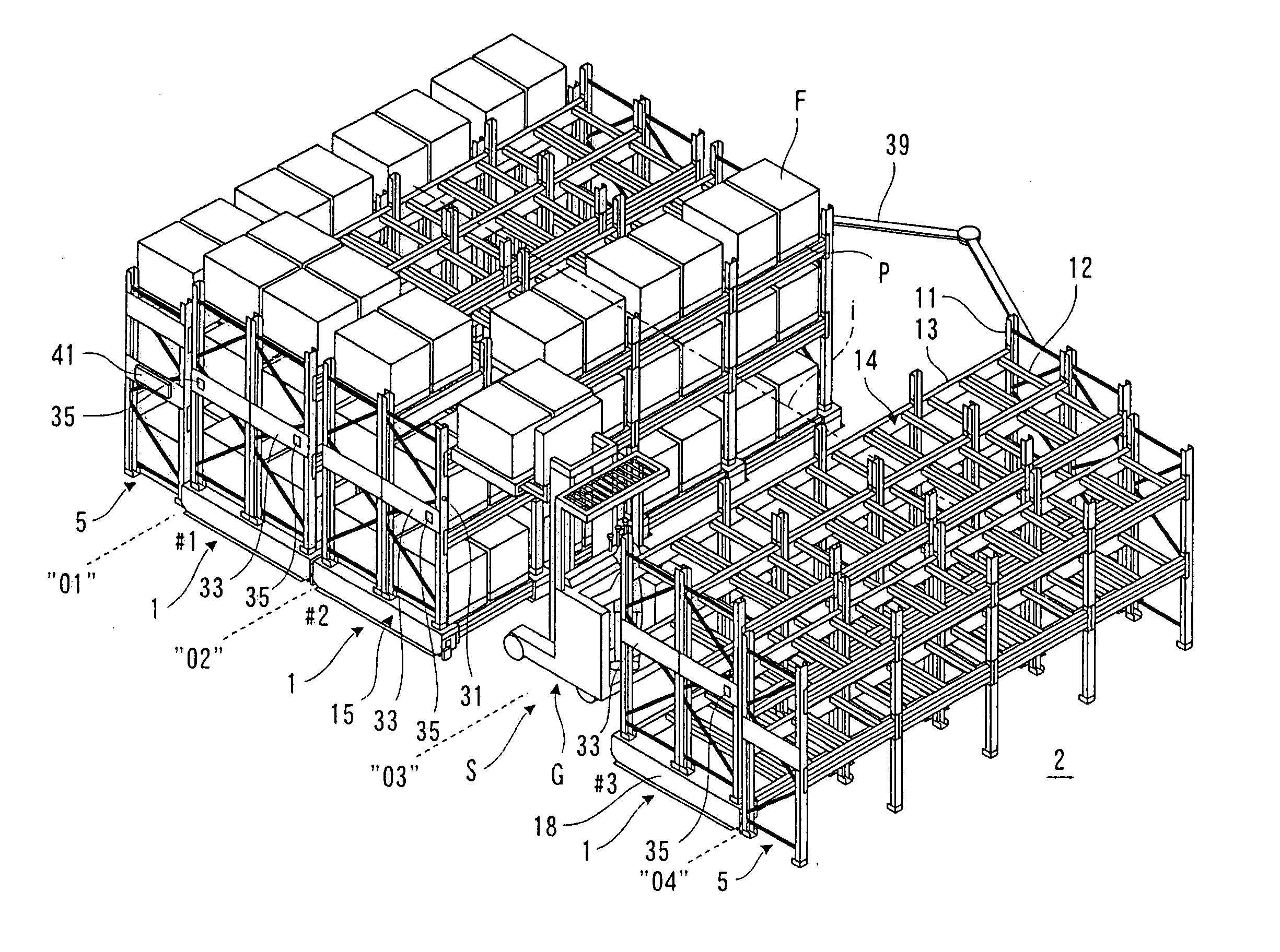
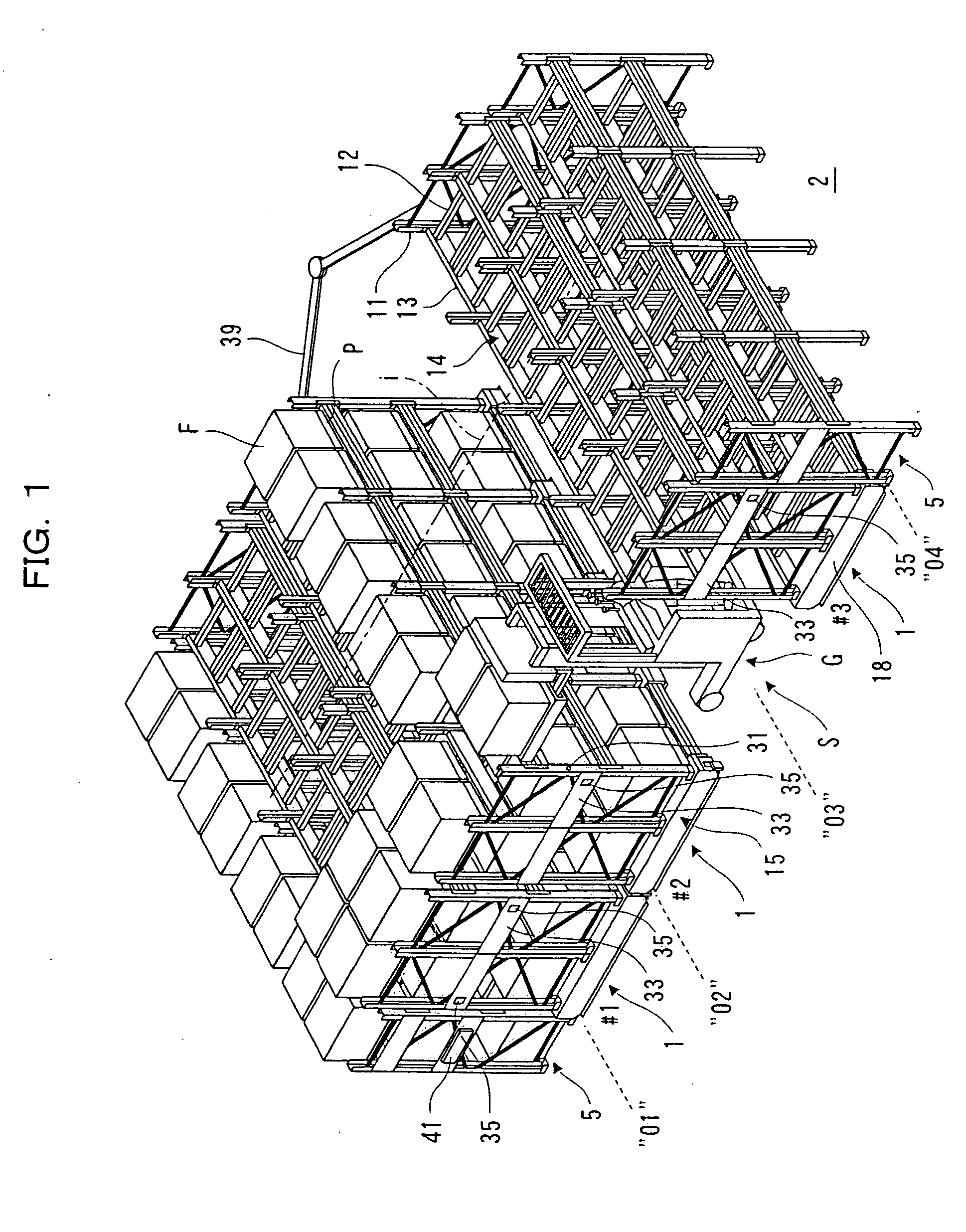
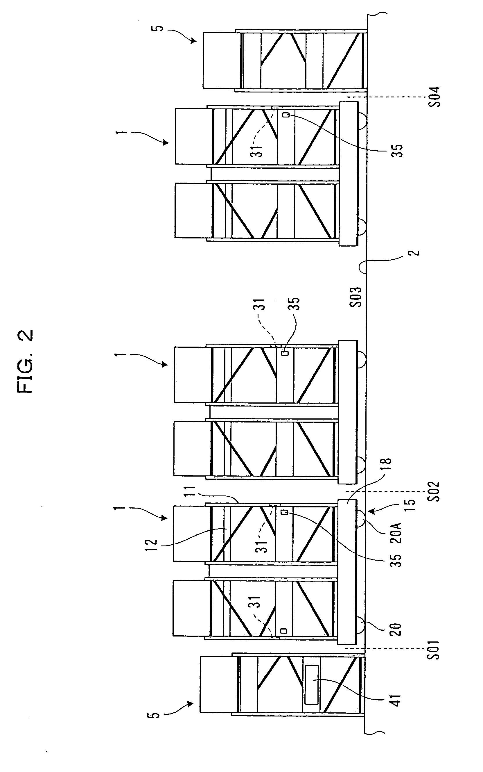
[0027]FIG. 1 is a perspective view of a shelving system according to an embodiment of the present invention; FIG. 2 is a front view of a movable shelf of the shelving system; FIG. 3 is a plan view of the movable shelf of the shelving system; FIG. 4 is a partially cut-out plan view of a main part of the movable shelf of the shelving system; and FIG. 5 is a side view of a travel supporting device and a movement detector of the movable shelf of the shelving system.

[0028] In FIGS. 1 to 5, a plurality (three in the figure) of a non-rail type movable shelves 1 (hereinafter, referred to as movable shelf) traveling back and forth in a free manner on a floor 2 along a constant travel path i by way of a travel supporting device (to be described later) is arranged on the floor 2. A fixed shelf 5 is arranged on both sides in a direction (hereinafter, referred to as a front-and-back direc...


PUM


Abstract

A shelving system including a plurality of movable shelves (1) installed for back-and-forth movement on a travel path through a travel support device, thereby to handle articles with respect to the movable shelves (1) opposed to a working aisle (S) by using the working aisle (S) opened between the movable shelves (1). Each movable shelf (1) includes a pair of movement detectors (19) disposed in a left-right direction (B) perpendicular to the travel direction (A) of the movable shelves (1). Absolute coordinates of each movement detector (19) are found based on detection signals from the pair of movement detectors (19) of each movable shelve (1). The amount of left-right directional deviation from the travel path (i) of the movable shelves (1) is corrected based on the amount of deviation of the absolute coordinates in the left-right direction (B). Further, the attitude of the movable shelves (1) is corrected to be perpendicular to the travel direction (A) based on positional deviation of the absolute coordinates in the travel direction (A), i.e. traveled distance deviation.

Description

TECHNICAL FIELD [0001] The present invention relates to a shelving system with a plurality of movable shelves. BACKGROUND ART [0002] Conventionally, the following configuration is proposed for the above type of shelving system. [0003] It is configured so that a constant travel path is arranged in a space within a warehouse or a business office, a plurality of shelves (movable shelves) installed for back and forth movement is arranged on the constant travel path leaving a space for a working aisle, a button for specifying the necessary working aisle when the working aisle is necessary between the movable shelves is provided on the movable shelf opposing, for example, the relevant working aisle, and one or a plurality of movable shelves self-advances along the constant travel path until the space between the movable shelves specified in accordance with the operation of the button reaches the width of the working aisle. Workers or cargo vehicles (e.g., fork lift) enter the working aisl...

Claims


Application Information

Patent Timeline
Patent Type & Authority Applications(United States)
IPC IPC(8): A47B53/02
CPCA47B53/02A47B53/00
Inventor HATANAKA, JOJI
Owner DAIFUKU CO LTD
Why Eureka
Try Eureka