Thermostat

Active Publication Date: 2005-10-13
NIPPON THERMOSTAT
View PDF2 Cites 23 Cited by
  • Summary
  • Abstract
  • Description
  • Claims
  • Application Information

AI Technical Summary

Benefits of technology

[0038] According to the present invention (invention of claim 1 to claim 4), since the outward flange unit provided to the opening end of the case constituting the operating member is used as the first valve disc for opening and closing the first fluid channel (main passage), in comparison to the conventional structure, the number of components is few, the assemblability and workability are superior, and costs can be reduced significantly.
[0039] According to the present invention (invention of claim 5 to claim 7), since the valve for opening and closing the second fluid channel (bypass channel) is constituted with a frame of the thermostat and the thermoelement, the number of components is few, the assemblability and workability are superior, and costs can be reduced.
[0040] Further, according to the present invention (invention of claim 5), since the valve for opening and closing the second fluid channel (bypass channel) is constituted with a cylindrical portion provided integrally with the device frame, and the tip of the cylindrical portion is connected to the bypass channel such that the fluid from the second fluid channel will only flow inward (or outward) inside the cylindrical portion, the fluid pressure caused by the

Problems solved by technology

With the thermostat device 5 employing a conventional structure, the bypass valve structure of the second valve disc 9 for opening and closing the bypass channel 3c is complex, and there are disadvantageous in that the number of components is numerous, assemblability is inferior, management of components is difficult, and there are problems in securing a reliable operation.
Thus, there were problems in that the number of components is numerous and the assemblability being inferior.
Further, with this kind of structure, precision of the respective components for press fitting is required, and problems would also arise in terms of workability.
In ad

Method used


Image

  • Thermostat
  • Thermostat
  • Thermostat

Examples


Example

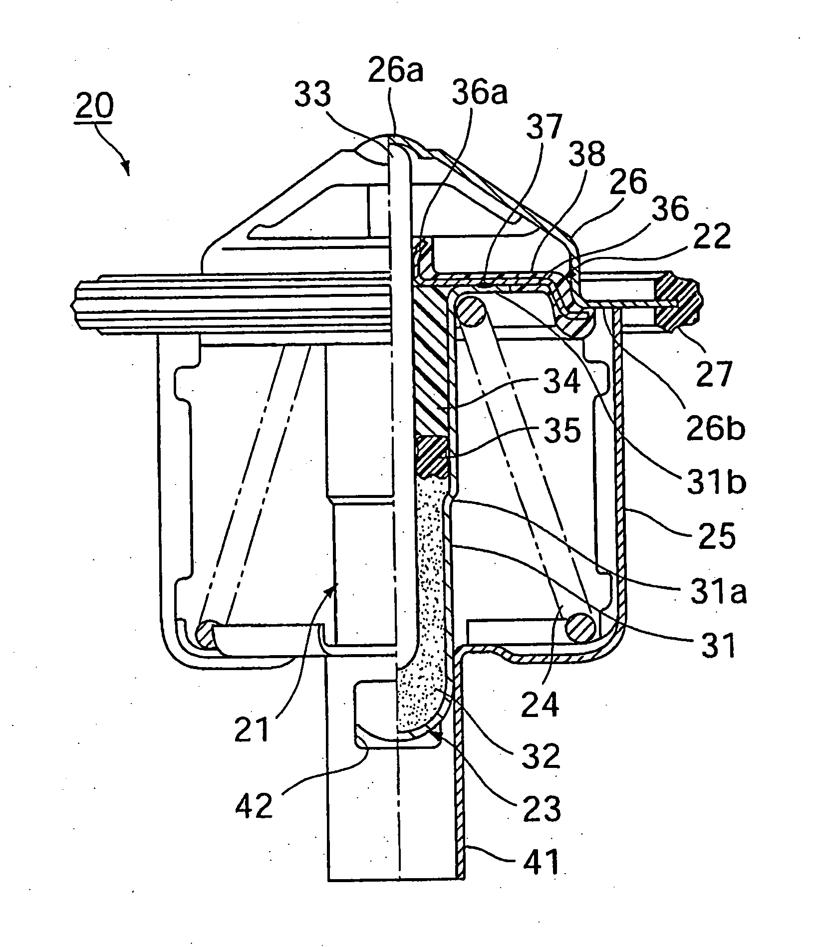
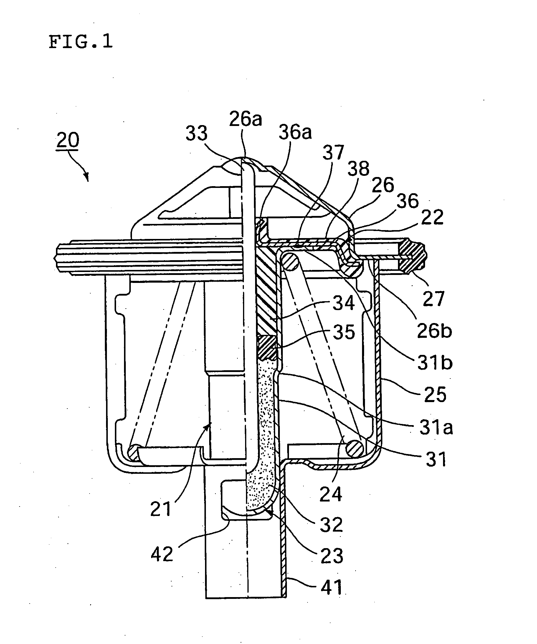
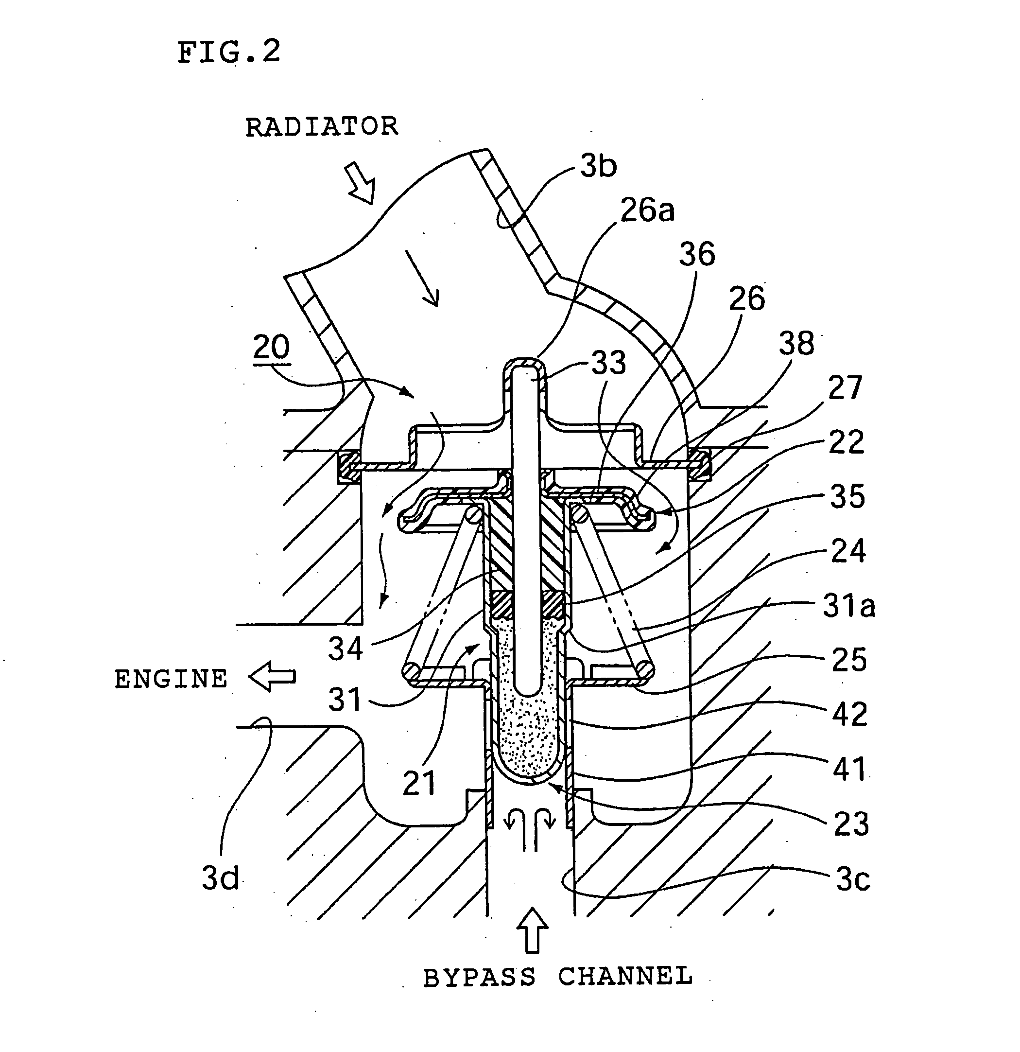
[0050]FIG. 1 to FIG. 5 show an embodiment of the thermostatic device pertaining to the present invention, and, in the present embodiment, explained is a case of the [thermostat device] being provided to the inlet side of the engine in an engine cooling system for controlling the coolant temperature.

[0051] In these diagrams, the thermostat device, which is a temperature-sensing automatic valve, represented with reference numeral 20, as evident from FIG. 2 and FIG. 6 illustrating the conventional example described above, is attached at the intersection of the cooling channel 3b on the radiator 2 side, and the bypass channel 3c from the engine outlet 1c side, and is used to selectively switch the flow of the coolant in the first and second fluid channels constituted with the foregoing passages and supplying such coolant to the cooling channel 3d leading to the engine inlet 1b. Here, an explanation is provided based on the assumption that the first fluid channel leads to the cooling ch...


PUM


Abstract

The object of the present invention is to obtain a thermostat device capable of improving the workability and assemblability, reducing costs, and downsizing the entire device with a minimum number of components. This thermostat device has a first valve disc 22 for opening and closing a first fluid passage 3b, and a second valve disc 23 for opening and closing a second fluid passage 3d, and constituted so as to open either the first fluid channel or second fluid channel and close the other by making the valve discs move integrally in conjunction with the operation of an operating member 21 in accordance with the temperature change of the fluid. The operating member has a case 31 which seals in one end side thereof a thermal expansion body 32 having a property of expanding and contracting in accordance with a temperature change, and retains a piston 33 from the opening of the other end side thereof in a freely reciprocable manner. The outward flange unit 36 provided to the opening on the other end side of the case is made to be the first valve disc.

Description

TECHNICAL FIELD [0001] The present invention relates to a thermostat device, which is a temperature-sensing automatic valve, to be used for controlling the coolant temperature by operating in accordance with the temperature change of the coolant and switching the flow of the engine coolant in an engine coolant circuit for circulating a coolant, which is used for cooling the internal combustion engine (hereinafter referred to as engine) used in automobiles and the like, between a cooling unit (hereinafter referred to as a radiator). BACKGROUND ART [0002] In an automobile engine, a cold-water cooling system employing a radiator is generally used for cooling such [engine]. From the past, in order to control the temperature of the coolant to be introduced into the engine in this type of cooling system, a thermostat employing a thermal expansion body for adjusting the amount of coolant to be circulated on the radiator side, or a valve unit for electrically controlling the same, is being ...

Claims


Application Information

Patent Timeline
IPC IPC(8): F01P7/16F16K11/02F16K31/00F16K31/68G05D23/13
CPCF01P7/16Y10T137/7737G05D23/134F16K31/002G05D23/1333
Inventor INOUE, FUJIO
Owner NIPPON THERMOSTAT
Why Eureka
Try Eureka