Cord-reel assembly for electronic devices

a technology of electronic devices and cords, applied in the direction of cleaning equipment, cable arrangements between relatively moving parts, coupling device connections, etc., to achieve the effect of convenient and simple manipulation

Inactive Publication Date: 2005-10-13
SAMSUNG GWANGJU ELECTRONICS CO LTD
View PDF14 Cites 7 Cited by
  • Summary
  • Abstract
  • Description
  • Claims
  • Application Information

AI Technical Summary

Benefits of technology

[0007] Accordingly, the present invention has been conceived to solve the above-mentioned problems occurring in the prior art, and an object of the present invention is to provide a cord-reel assembly for an electronic device with an improved construction allowing a user to conveniently and simply manipulate the cord-reel assembly for winding a cord.
[0009] In the preferred embodiment, the damper comprises an external casing inserted into an axial hole in the manipulation lever. An internal casing installed within the external casing is rotatable in relation to the external casing on a rotary shaft which is the pivotal center of the manipulation lever. An interference fluid fills space between the external casing to interfere with the relative rotation between the internal casing and the external casing. When the cord reel assembly brake member is released, a spring in the cord reel assembly begins to re-wind the cord. The damper slows the engagement of the brake member to the cord reel assembly, allowing the cord reel assembly to re-wind a cord before the brake member re-engages the cord reel.

Problems solved by technology

An interference fluid fills space between the external casing to interfere with the relative rotation between the internal casing and the external casing.

Method used


Image

  • Cord-reel assembly for electronic devices
  • Cord-reel assembly for electronic devices
  • Cord-reel assembly for electronic devices

Examples


Embodiment Construction

[0016] Hereinbelow, embodiments of the present invention will be described in detail with reference to the accompanying drawings.

[0017] In the following description, reference numerals are used for the same elements in different drawings. The matters defined in the description such as a detailed construction and elements are only examples and are not to be construed as limiting claim scope. Well-known functions or constructions are omitted for brevity since they might obscure the invention disclosed and claimed herein in unnecessary detail.

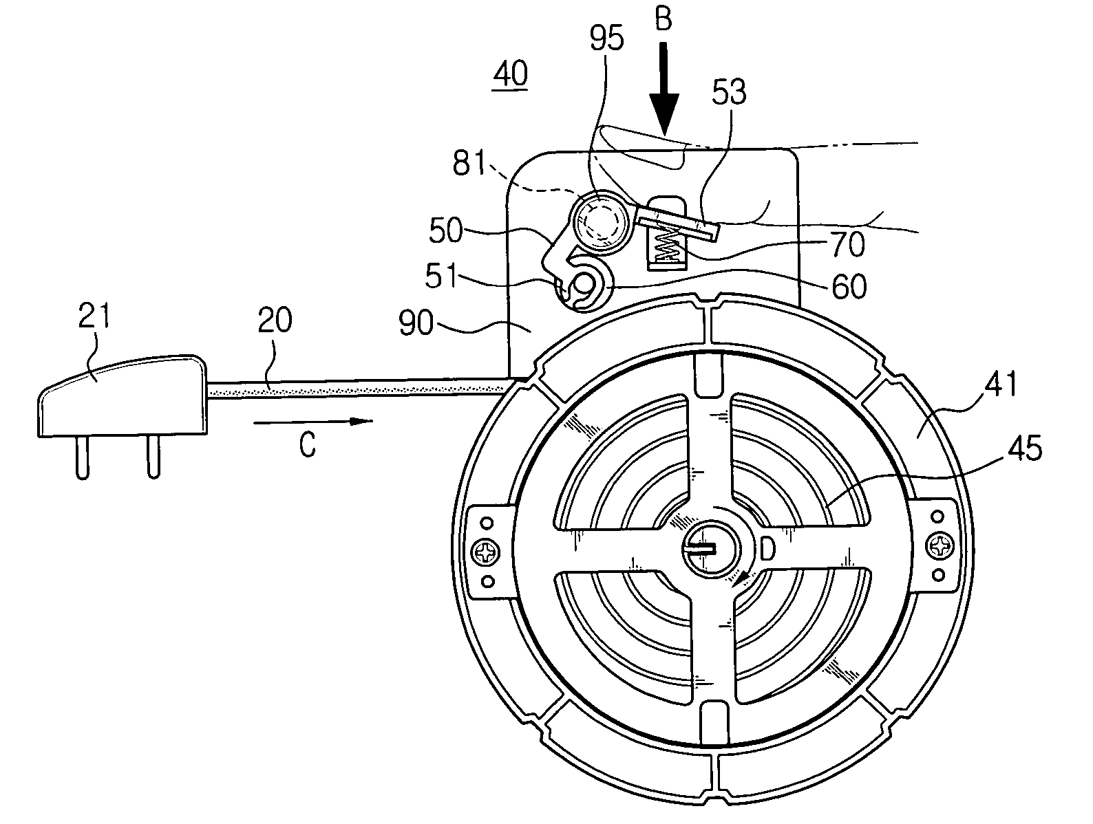
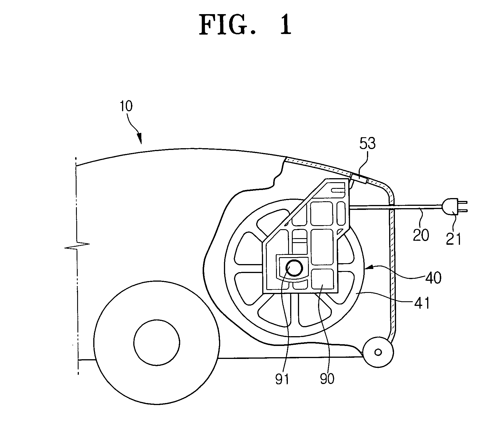
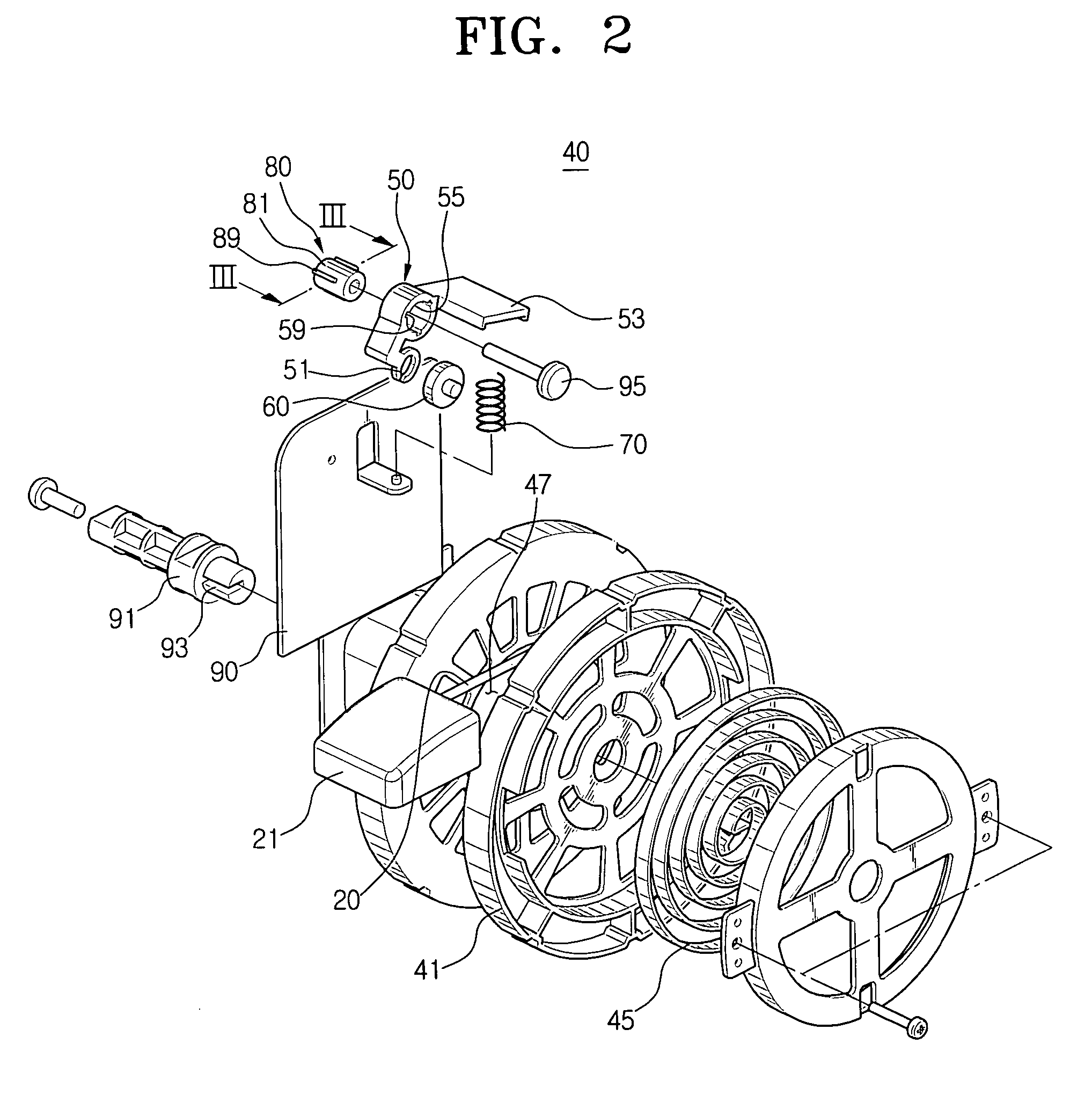
[0018]FIG. 1 shows part of a vacuum cleaner or other electronic device 10 that is provided with a cord-reel assembly according to an embodiment of the present invention. The cord-reel assembly 40 is installed within the electronic device 10, by which a cord 20 for supplying electric power to the electronic device 10 is selectively and automatically wounded around a cord-reel body 41 on which the cord 20 is stored.

[0019] In the drawing, a reel c...


PUM


Abstract

A cord-reel assembly comprises a cord-reel body rotatably installed in the electronic device, a brake member capable of selectively contacting with the cord-reel body, so that the brake member selectively restrains the rotation of the cord-reel body, a manipulation lever having a coupling part connected to the brake member, wherein the coupling part is moved between a first position at which the brake member is contacted with the cord-reel body by the manipulation of the manipulation lever by a user and a second position at which the brake member is spaced from the cord-reel body, a elastic member for elastically biasing the manipulation lever so that the coupling part is moved to the first position, and a damper unit for interfering with the movement of the coupling part in such a way that the returning velocity of the coupling part is delayed when the coupling part is returned from the second position to the first position by the elastic member. With this arrangement, a user does not have to continuously actuate the cord reel until the cord is completely wound.

Description

CROSS-REFERENCE TO RELATED APPLICATIONS [0001] This application claims the benefit of Korean Patent Application No. 2004-25178, filed Apr. 13, 2004, in the Korean Intellectual Property Office, the disclosure of which is incorporated herein by reference. BACKGROUND OF THE INVENTION [0002] The present invention relates generally to an electronic device, and more particularly, to a cord-reel assembly for winding a cord for supplying electric power to an electronic device, which allows the cord to be elastically drawn out from the electronic device. [0003] Prior art cord-reel assemblies comprise a cord-reel body, a manipulation lever, and a brake member that slows and / or locks the cord-reel body. [0004] As is known, the cord-reel member is rotatably installed within an electronic device where it conveniently operates to store a cord within an electronic device. The manipulation lever actuates the cord-reel body brake member to selectively contact or engage with the cord-reel body or the...

Claims


Application Information

Patent Timeline
Patent Type & Authority Applications(United States)
IPC IPC(8): B65H75/44B65H75/38H02G11/02H01R13/60B65H75/34B65H75/30A47L9/26B65H75/48B65H75/42
CPCA47L9/26B65H75/4431H05B1/0222H05B3/20A47C21/048
Inventor PARK, JOUNG-SOO
Owner SAMSUNG GWANGJU ELECTRONICS CO LTD
Why Eureka
Try Eureka