Method for making a laminated structure and aircraft provided with such a structure

a technology of which is applied in the field of making laminated structures and aircraft provided with such structures, can solve the problems of plastic deformation of metal plates, greater life of fasteners, and cases of delamination of panels

Inactive Publication Date: 2005-10-13
AIRBUS OPERATIONS (SAS)
View PDF4 Cites 31 Cited by
  • Summary
  • Abstract
  • Description
  • Claims
  • Application Information

AI Technical Summary

Problems solved by technology

This force-fitting leads to a plastic deformation of the metal plates in the vicinity of these bore-holes.
In fact, the greater the interference, the greater the lifetime of the fastener.
Indeed, it has been observed that it leads to cases of delamination of the panel at the position of the bore-hole.
In practice, at this place, the panel becomes we

Method used


Image

  • Method for making a laminated structure and aircraft provided with such a structure
  • Method for making a laminated structure and aircraft provided with such a structure

Examples


Embodiment Construction

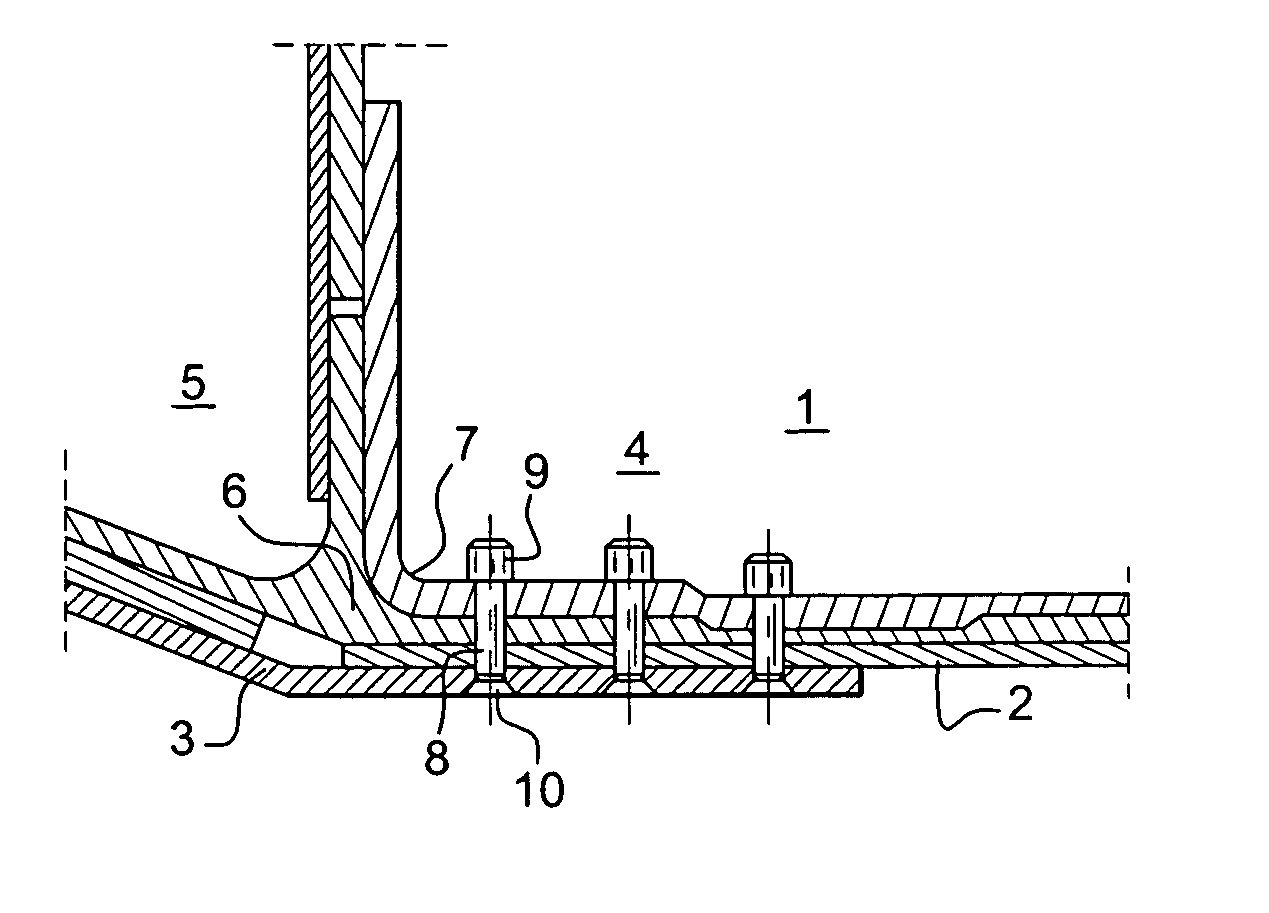
[0022]FIG. 1 shows a laminated structure 1 obtained by means of a stack containing at least one panel 2 made of a composite material and, in this case, a plate 3 made of metal, for example aluminum. The stack may comprise several composite panels placed flat against one another. In the example, the structure 1 represents a bond between a central fuselage box 4 of an aircraft and a wing unit 5. In practice here, the panel 2 is furthermore counter-secured by a triple corner-piece 6 made of aluminum. The corner-piece 6 is itself held by a single corner-piece 7. The corner-piece 6 and the plate 3 sandwich the panel 2. These different parts are joined together by fasteners such as 8. These fasteners 8 are positioned as follows. The panel 2 and the plate 3, or the panel 2, the plate 3 and the corner-pieces 6 and 7, are held together by auxiliary means. While they are held, their stack is drilled with a bore-hole through which the fastener 8 is supposed to pass. Then this fastener is intro...


PUM

PropertyMeasurementUnit
Fractionaaaaaaaaaa
Fractionaaaaaaaaaa
Diameteraaaaaaaaaa

Abstract

To make a laminated structure comprising a panel made of composite materials and placed flat against at least one metal plate, the panel and the plate are presented in a stack, this stack is drilled to form a fastening borehole, a fastening rod is introduced into the bore and the fastener is fixed. In the invention, during the drilling, a negative clearance is made between a diameter of the bore and a diameter of the fastener, and when the fastener is being introduced, it is introduced from the metal plate. This mode of action prompts a positive interference that promotes the lasting nature of the fastener.

Description

RELATED APPLICATION [0001] The present application claims priority to French Application No. 03 50976 filed Dec. 4, 2003. BACKGROUND OF THE INVENTION [0002] 1. Field of the Invention [0003] An object of the present invention is a method for making a laminated structure and an aircraft provided with such a structure. More particularly, its field is that of aircraft construction. However, the invention can be applied in other fields. The aim of the invention is to contribute to the making of a more robust laminated structure. [0004] 2. Description of the Prior Art [0005] Aircraft structures, typically wing units or fuselages, are built out of panels made of composite materials. For example, these panels are carbon fiber panels. These panels have the advantage of being light and particularly resistant. There are known ways of assembling such panels together to achieve substantial thickness values in the range of 110 mm to 200 mm. There also exist known ways of butt-jointing such panels...

Claims


Application Information

Patent Timeline
IPC IPC(8): B64C1/00B64C1/26F16B4/00F16B5/02F16B5/04
CPCB64C1/06B64C1/12B64C1/26B64C2001/0072B64C2001/0081F16B4/004Y10T428/24174F16B5/04Y10T29/49945Y10T29/49629Y02T50/43Y10T29/49947Y10T29/49622F16B5/025Y02T50/40
Inventor GUITTARD, DOMINIQUECABANAC, JEAN-PIERREROGER, JANY
Owner AIRBUS OPERATIONS (SAS)
Why Eureka
Try Eureka