
Air car

a technology for air vehicles and motor vehicles, applied in the direction of convertible aircraft, vehicle components, steps arrangement, etc., can solve the problems of increasing the number of motor vehicles in the world, and achieve the effects of reducing the fluctuation of the lift force available, reducing the number of motor vehicles, and increasing the lift for

Inactive Publication Date: 2005-10-13
TOMOYASU YOSHIOKI
View PDF7 Cites 1 Cited by
  • Summary
  • Abstract
  • Description
  • Claims
  • Application Information

AI Technical Summary

Benefits of technology

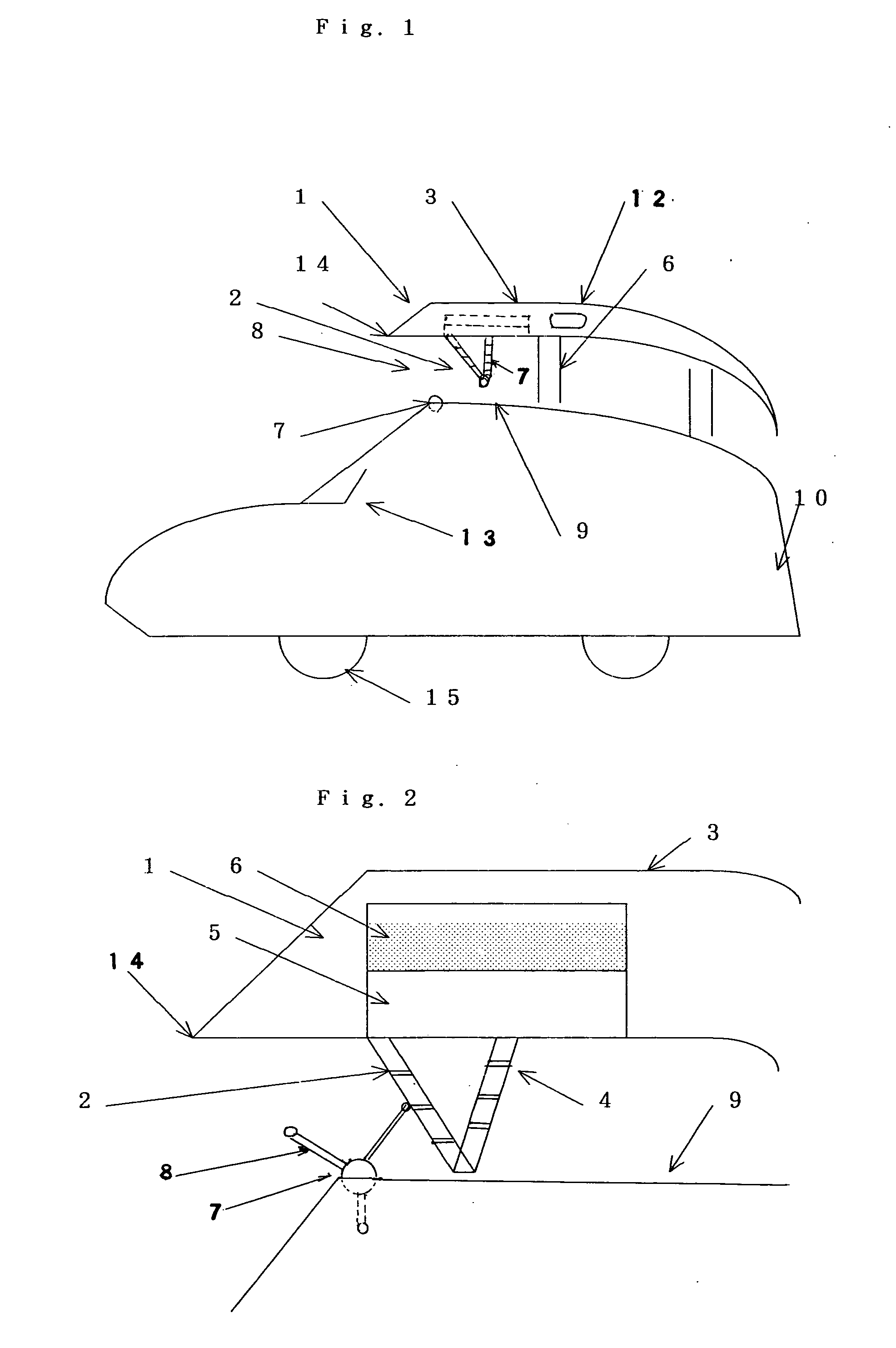
[0003] The invention is generally directed to provide the vehicle with the lift force for enabling to drive in the air by use of a hydraulic apparatus to multiply the lift force converted by the head wind caused by either engine or motor thereof without any additional energy sources involved, thus saving production as well as running costs and resulting at solving the problems of air pollution, traffic jam and accidents. The mechanism of the system of this invention is designed to operate said hydraulic apparatus installed inside of the cover wing over the roof thereof geared with the motion of a connecting rod connected with the lever fence fitted with bores guiding air flow to pass through to be fluctuated up and down in repeated operations subject to the rotating operation of the blades ejecting outwards from the shaft of the windmill equipped with the front roof thereof to be rotated by the force of head wind caused by the propulsive operation of either engine or turbine or motor thereof. In case where said lever fence connected with the connecting rod is designed to be fluctuated ups and downs continuously subject to the shift of said rotating blade of the windmill, it is possible to damp out the fluctuation of the lift force available for the vehicle driven in the air that the plural units of the hydraulic apparatus is situated being arranged either in parallel or lengthwise with different phase of blades of the windmill. On the other hand, the vehicle is designed to be handles with a control stick capable of driving in the air as well as on the ground with a plate attached on the side walls sharing the function of rudders and flaps just like the oar to the boat.

Problems solved by technology

On the background that there are a remarkable tendency for increasing the number of the motor car in the world, many problems on such as the grobal environment, air pollution, traffic jam and the like happen to appear.

Method used


Image

  • Air car
  • Air car

Examples


Embodiment Construction

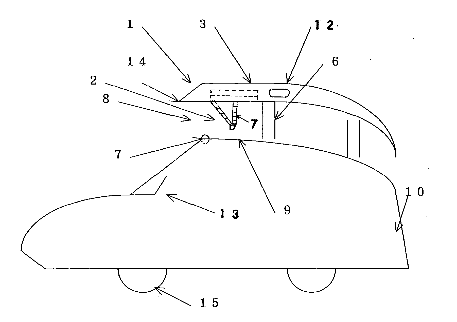
[0007] As shown FIG. 1 and FIG. 2, the air car is equipped with the hydraulic apparatus (1) accommodated inside a cover wing (3) propped over the roof (9) thereof consisting of the hydraulic cylinder (5) and the hydraulic oil (6) to convert the head wind caused by either engine (10) or motor of the motor car into lift force to be multiplied by the function thereof Said hydraulic apparatus (1) is designed to be operated by the connecting rod (4) geared with the motion of the lever fence (2) fitted with some bores guiding air flow to pass through and to be raised by blades (8) which are radially ejected outwards from the shaft of the windmill (7) rotated by the headwind thus eliminating the need for any electric appliance such as ordinary hydraulic apparatus, and available at considerable low cost. Said hydraulic apparatus (1) is designed to push upward said hydraulic cylinder (5) to deliver the force transmitted through the connecting rod (4) linked with the lever fence (2) to be rai...


PUM


Abstract

The invention is directed to drive the motor car into the air with the lift force produced by the head wind caused by either engine or motor to rotate the blades of windmill equipped with on the roof thereof geared with the lever fence fitted with bores to be passed through by the air connected with the connecting rod to operate the hydraulic apparatus to produce and multiply the lift force accommodated inside the cover wing of which trailing edge is inclined to produce lift independently in the propulsive operation and with the thrust made by either engine or motor.

Description

FIELD OF THE INVENTION [0001] The present invention is generally directed to providing the motor car with the lift force strong enough to drive in the air taking advantage of head wind generated by either engine or motor thereof. BACKGROUND OF THE INVENTION [0002] On the background that there are a remarkable tendency for increasing the number of the motor car in the world, many problems on such as the grobal environment, air pollution, traffic jam and the like happen to appear. Therefore, it is required to solve the problems urgently. SUMMARY OF THE INVENTION [0003] The invention is generally directed to provide the vehicle with the lift force for enabling to drive in the air by use of a hydraulic apparatus to multiply the lift force converted by the head wind caused by either engine or motor thereof without any additional energy sources involved, thus saving production as well as running costs and resulting at solving the problems of air pollution, traffic jam and accidents. The m...

Claims


Application Information

Patent Timeline
IPC IPC(8): B60R3/00
CPCB64C37/00
Inventor TOMOYASU, YOSHIOKI
Owner TOMOYASU YOSHIOKI
Learn More