Bulb type electrodeless discharge lamp and electrodeless discharge lamp lighting device

a discharge lamp and light source technology, which is applied in the direction of discharge tube luminescnet screens, magnetic discharge control, lighting and heating apparatus, etc., can solve the problems of the bulb becomes higher, and it takes not less than several minutes of rising time to obtain sufficient brightness from the lamp. , to achieve the effect of suppressing the convection of the discharge gas and high frequency power

Inactive Publication Date: 2005-10-13
PANASONIC CORP
View PDF9 Cites 5 Cited by
  • Summary
  • Abstract
  • Description
  • Claims
  • Application Information

AI Technical Summary

Benefits of technology

[0012] According to one aspect of the present invention, a first compact self-ballasted electrodeless discharge lamp includes a bulb filled with discharge gas containing mercury and a rare gas; an excitation coil installed near the bulb; a ballast circuit which supplies high frequency power to the excitation coil; and a base that is electrically connected to the ballast circuit, and in this structure, the bulb, the excitation coil, the ballast circuit and the base are formed into an integral part; the bulb has a virtually spherical shape or a virtually ellipsoidal shape; a recessed portion to which the excitation coil is inserted is formed on the ballast circuit side of the bulb; the recessed portion has an opening section on the ballast circuit side, and has a tube shape with a virtually round shape in its cross section, with a portion positioned on the side opposite to the opening section of the recessed portion being provided with a function for suppressing the convection of the discharge gas; the largest diameter of the bulb is set in a range from not less than 60 mm to not more than 90 mm; the bulb wall loading of the bulb during a stable lighting operation is set in a range from not less than 0.07 W / cm2 to not more than 0.11 W / cm2; the ratio (h / D) of the height (h) of the bulb based upon the end face of the opening section in the recessed portion to the largest diameter (D) of the bulb is set in a range from not less than 1.0 to not more than 1.3; and, supposing that a distance between a top face of the recessed portion positioned on the side opposite to the opening section of the recessed portion and a top portion of the bulb facing the top face of the recessed portion is Δh, and that a diameter of a portion positioned on the side opposite to the opening section of the recessed portion is Dc, the following relationship is satisfied: Δh≦1.15×Dc+1.25 [mm].

Problems solved by technology

For this reason, upon operating, the temperature of the bulb becomes higher, and it is difficult in principle to set the temperature of the bulb to the vicinity of 40° C. In other words, in comparison with the straight tube fluorescent lamp and the like, the compact self-ballasted fluorescent lamp has a greater power per unit surface area, with the result that heat radiation from the lamp surface is not carried out sufficiently to cause a high temperature in the bulb.
In the method using the amalgam, however, in the case when a lamp is turned on from a turn-off state in which the lamp temperature is low, since it takes some time until the amalgam has had a temperature rise to again release the adsorbed mercury, the resulting problem is that it takes not less than several minutes of rising-time to obtain sufficient brightness from the lamp after the turning-on.
Moreover, in the case of a method in which, in order to shorten the rising-time of brightness, without using amalgam, the bump portion is formed on the outer wall of the bulb with mercury droplets being enclosed in the bulb, although the effect for controlling the temperature of the coldest point to the vicinity of 40° C. is obtained, the glass strength of the bump portion tends to weaken to be easily broken.
Furthermore, since the incandescent lamp has no bump portion of this type, it is not desirable from the aesthetic viewpoint, when this fluorescent lamp is used in place of an incandescent lamp.

Method used


Image

  • Bulb type electrodeless discharge lamp and electrodeless discharge lamp lighting device
  • Bulb type electrodeless discharge lamp and electrodeless discharge lamp lighting device
  • Bulb type electrodeless discharge lamp and electrodeless discharge lamp lighting device

Examples


Embodiment Construction

[0040] The inventors of the present invention have repeated many experiments, and found an optimal range of dimensions of constituent elements inside a lamp, which can control the temperature of the coldest point to a desirable range, without using amalgam, without giving any adverse effects to the appearance of the lamp.

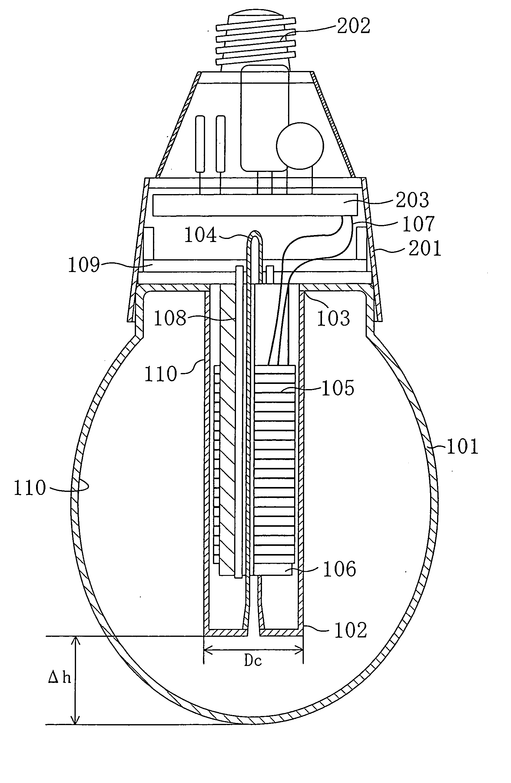
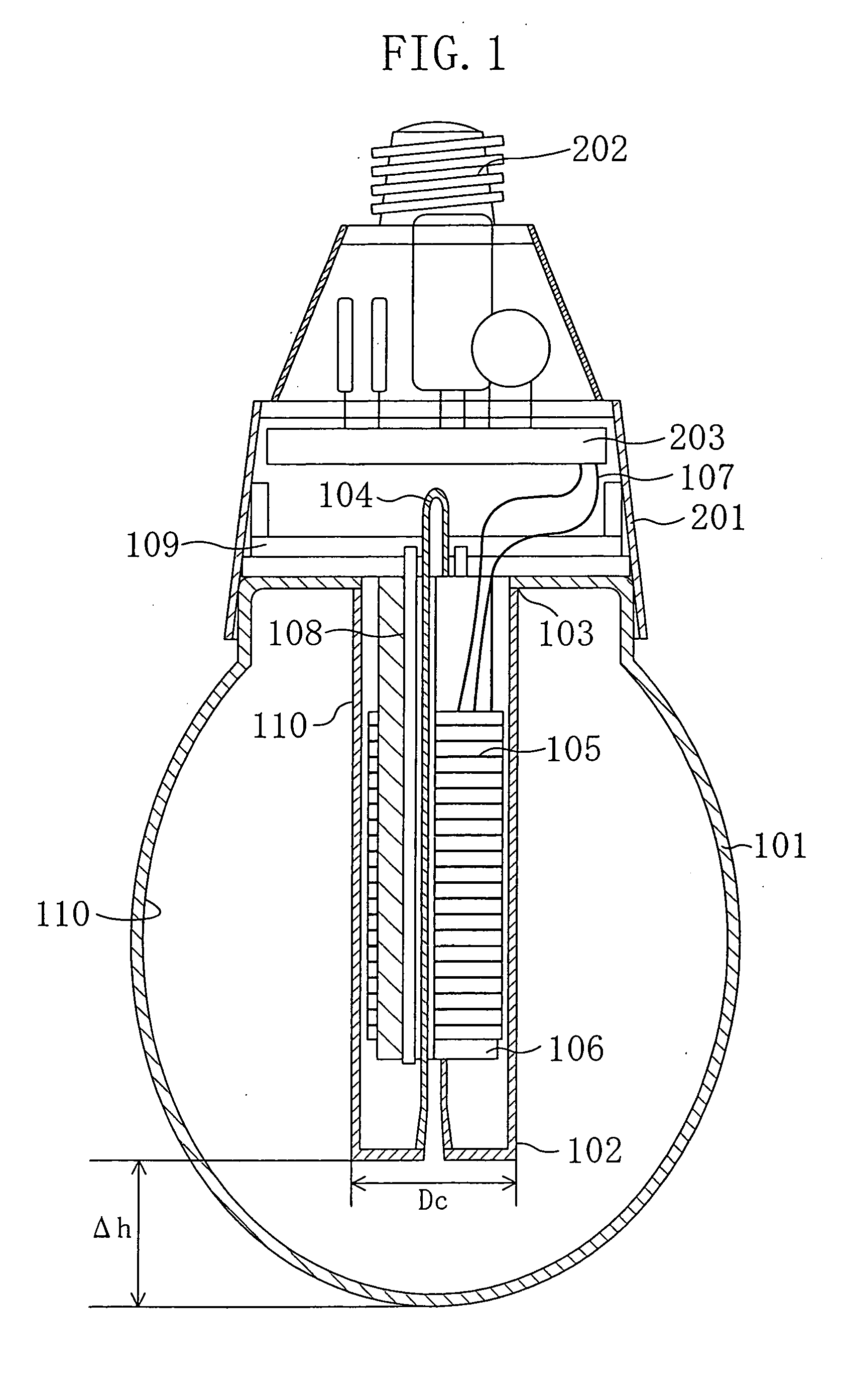
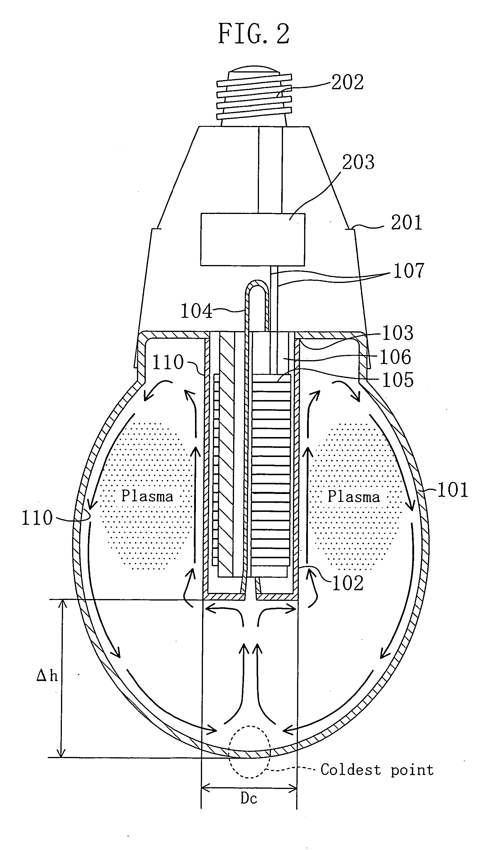
[0041] Referring to FIG. 2, the following description will discuss how the temperature of the coldest point of the bulb is determined during a stable lighting operation. FIG. 2 shows a state in which an electrodeless fluorescent lamp is being lit with “a base (high-frequency power-supply circuit 203 and a base 202) facing up” (hereinafter, this state is referred to as “base-up lighting state”). Normally, an incandescent lamp is used in this base-up lighting state. In FIG. 2, a bulb 101 has a virtually ellipsoidal shape that is similar to an incandescent lamp having an A-type shape defined under JIS C 7710-1988, and is made from light-transmitting glass, for example...


PUM


Abstract

A bulb type electrodeless discharge lamp, comprising a recessed part (102), wherein the maximum diameter of a light emitting tube (101) is 60 to 90 mm and the tube wall load of the light emitting tube (101) is 0.07 to 0.11 W/cm2, and a relation between the diameter Dc of the recessed part (102) and an interval Δh between the top of the recessed part (102) and the top part of the light emitting tube (101) meets the requirement of Δh≦1.15×Dc+1.25 [mm].

Description

FIELD OF THE INVENTION [0001] The present invention relates to a compact self-ballasted electrodeless discharge lamp and an electrodeless-discharge-lamp lighting device. BACKGROUND OF THE INVENTION [0002] In recent years, from the viewpoints of global environment protection and economical efficiency, compact self-ballasted fluorescent lamps with electrodes, which are about five times higher in efficiency in comparison with incandescent lamps and also have an operating life time about six times longer than that of incandescent lamps, have been widely used in houses, hotels and the like in place of incandescent lamps. Moreover, recently, in addition to conventionally-used compact self-ballasted fluorescent lamps with electrodes, electrodeless compact self-ballasted fluorescent lamps have been utilized. Since the electrodeless fluorescent lamp, which has no electrodes, has an operating life time that is about two times longer than that of a fluorescent lamp with electrodes, it is expec...

Claims


Application Information

Patent Timeline
Patent Type & Authority Applications(United States)
IPC IPC(8): F21Y101/00F21Y103/37H01J65/04
CPCH01J65/048
Inventor HASHIMOTODANI, KIYOSHIARAKAWA, TAKESHIHOCHI, AKIRAKATASE, KOICHIOMATA, YUUJIHAGIWARA, YOSHIHISA
Owner PANASONIC CORP
Why Eureka
Try Eureka