Weapon sight

US20050225853A1Active Publication Date: 2005-10-13AIMPOINT AB

Image

  • Weapon sight
  • Weapon sight
  • Weapon sight

Examples


Embodiment Construction

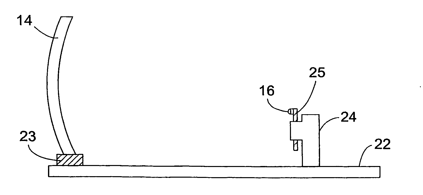
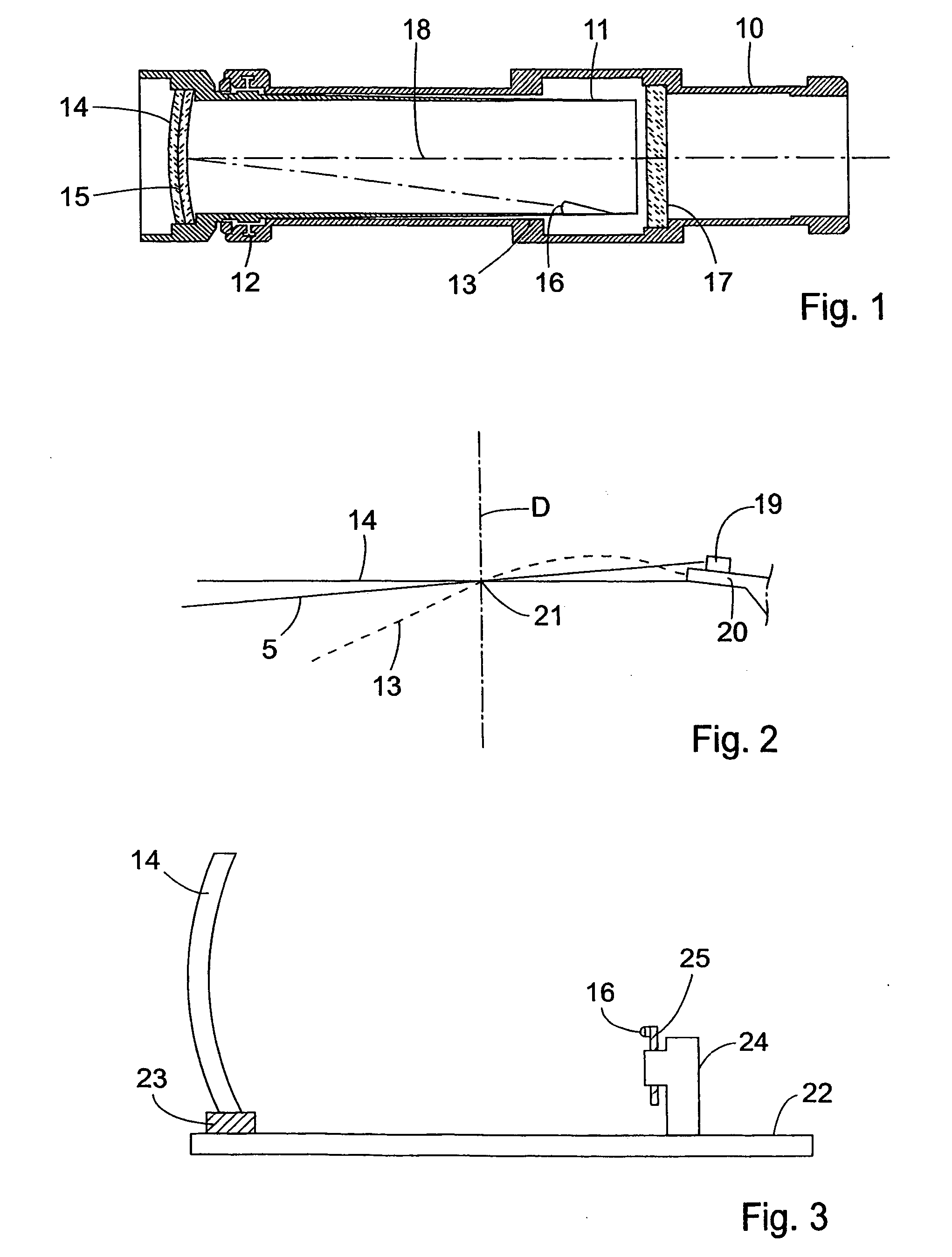
[0020] The weapon sight disclosed in FIG. 1 is of a well known prior art embodiment comprising a light channel formed by an outer tube 10 to be fastened to the barrel, the breechblock, or a specially designed sight holder of a weapon on which the sight shall be used, and an inner tube 11 which is mounted in the outer tube at one end 12 and is fixed at the other end by adjustment means 13, allowing adjustment of the longitudinal axis of the inner tube horizontally and vertically in relation to the longitudinal axis of the outer tube as is necessary in order to adapt the sight to the weapon on which it is used. In said one end of the inner tube a double lens 14 is provided having a layer 15 between the lenses, said layer reflecting red light. Inside the inner tube a light source 16 e.g. an LED (Light Emitting Diode) or RCLED (Resonant Cavity Light Emitting Diode) is mounted to project a beam of red light with minimal dispersion on layer 15 where the light beam forms a red spot to be u...


PUM


Abstract

A weapon sight of the kind comprising a lens having a partially reflecting surface, a light source spaced from the lens for emitting light towards said reflecting surface to produce a light spot by direct imaging of said light source on said surface to be superimposed on a target when sighting through the lens. For adjustment of the location of the light spot on the reflecting surface when observed from a defined fixed position, the sight includes a device for displacement of the light source, comprising a miniature drive motor or element operatively connected with the light source.

Description

FIELD OF THE INVENTION [0001] The invention relates to a weapon sight to be used on rifles, guns, and machine guns. [0002] The weapon sight is of the kind comprising a lens having a partially reflecting surface; a light source spaced from the lens for emitting light towards said reflecting surface to produce a light spot by direct imaging of said light source on said surface to be superimposed on a target when sighting through the lens; and means for adjustment of the location of the light spot on the reflecting surface when observed from a defined fixed position, by displacement of the light source. [0003] A weapon sight of the kind referred to is disclosed in GB-A-2 292 465. [0004] Usually, the lens is located at one end of a light channel formed by an elongate housing, and the light source is located in the channel. At sighting, the light spot and the target are observed through the light channel from the other end thereof. BACKGROUND OF THE INVENTION [0005] If the sight at zeroi...

Claims


Application Information

Patent Timeline
13 Oct 2005
Publication
US20050225853A1
IPC
F41G1/30; G02B23/10
CPC
F41G1/30; G02B23/10; F41G3/08; F41G3/06
Inventors
HAKANSSON, HAKAN; WIKLUND, RALF