Method and system for extensible position location

a positioning system and method technology, applied in direction finders, direction finders using radio waves, instruments, etc., can solve the problems of time-critical setting up a positioning system, the known uwb system suffers from various problems, and the conventional system does not allow for the quick addition of a new reference node, so as to extend the ability of the system

Active Publication Date: 2005-10-13
PLUS LOCATION SYST PTY
View PDF4 Cites 206 Cited by
  • Summary
  • Abstract
  • Description
  • Claims
  • Application Information

AI Technical Summary

Benefits of technology

[0008] According to the present invention, there is provided an extensible positioning system. In embodiments, the system may include sets of primary reference nodes, secondary reference nodes, and non-fixed nodes. Ranging is performed between the primary and reference nodes to determine the positions of the secondary reference nodes. The secondary reference nodes thereby extend the ability of the system to perform ranging with non-fixed nodes.

Problems solved by technology

However, known UWB systems suffer from various problems.
Conventional systems do not allow for a quick addition of a new reference node to the positioning system.
This may cause problems where setting up a positioning system is time critical, such as in firefighting or warfare.
Additionally, conventional methods of determining the position of a non-fixed radio have insufficient accuracy and may have difficulty in resolving the position of a reference radio, particularly in situations when the radio is moving or which a GPS signal is blocked such as indoors.
Moreover, traditional positioning architectures neither readily accept UWB radios nor incorporate their capabilities.
Additional problems in conventional UWB systems are caused by multipath characteristics of UWB signals.
However, these assumptions are not always correct.
In such a situation, a leading edge detection approach that assumes the leading edge corresponds to the location in the signal having the maximum amplitude may incorrectly determine the location of the leading edge.
Incorrect determination of the leading edge results in error in the timing measurement, which translates into an incorrectly determined distance between the reference radio and the target radio that, when combined with other distance measurements between the target radio and other reference radios, further translates into an incorrectly determined position of the target radio.

Method used


Image

  • Method and system for extensible position location
  • Method and system for extensible position location
  • Method and system for extensible position location

Examples


Embodiment Construction

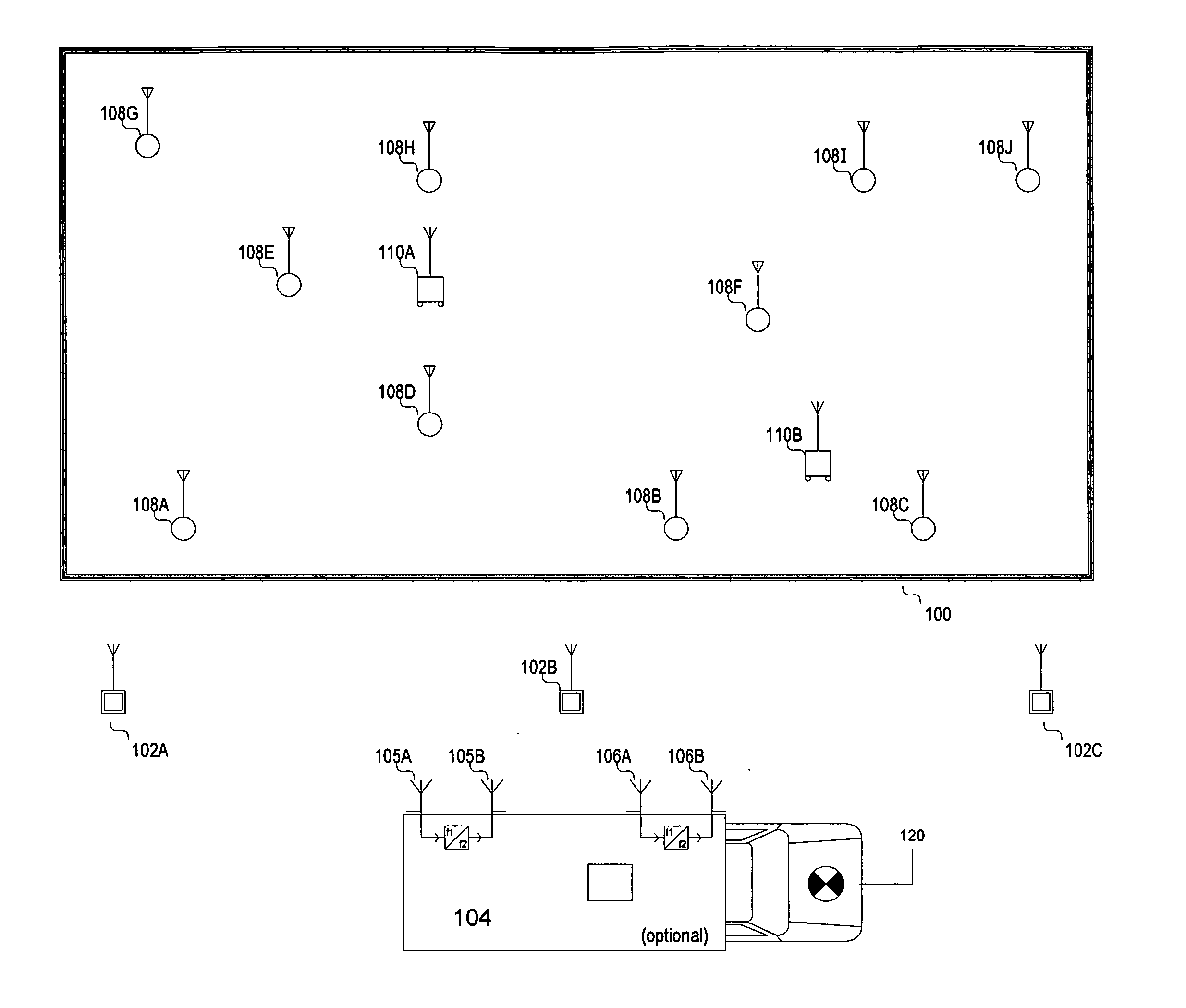
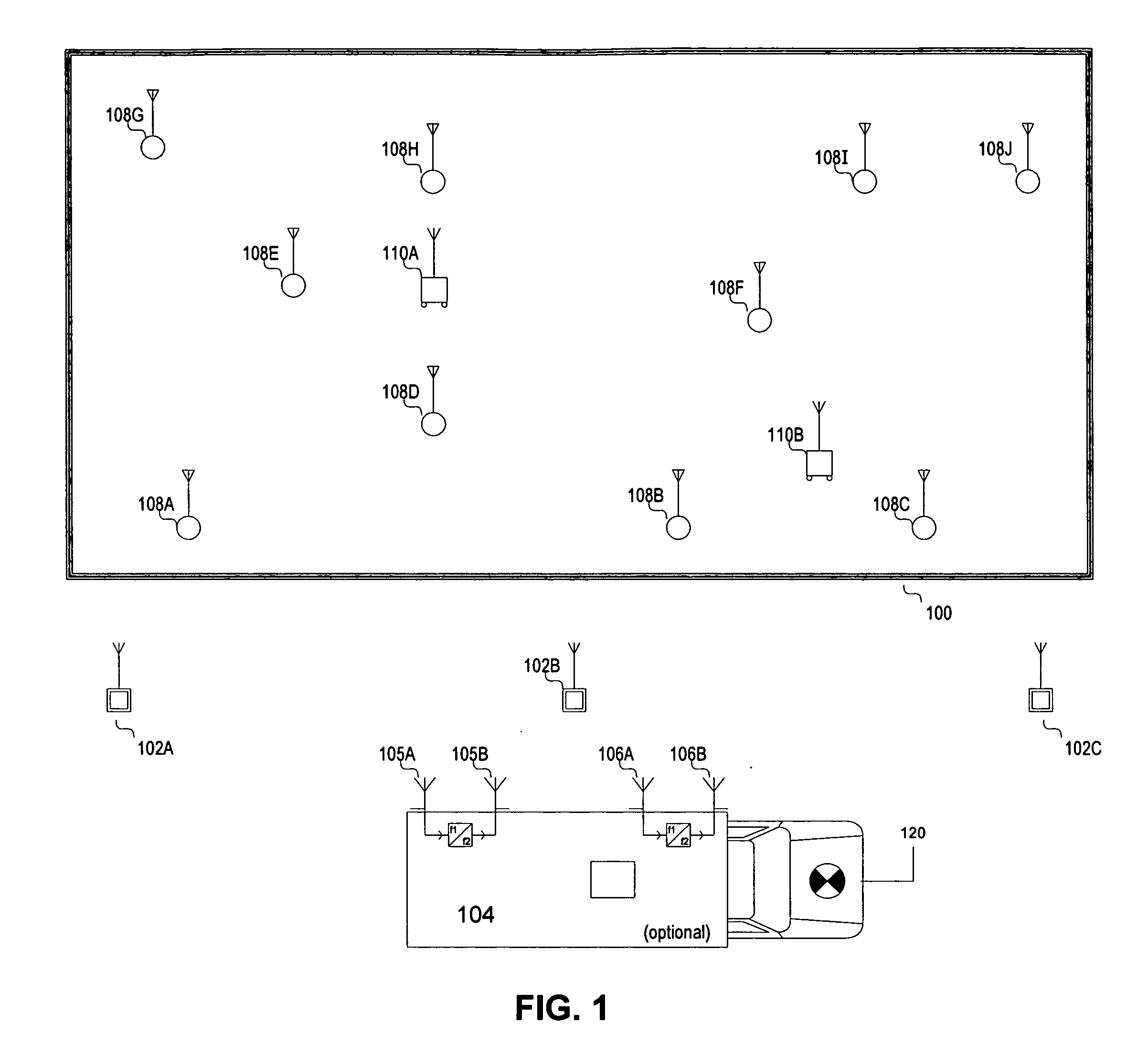
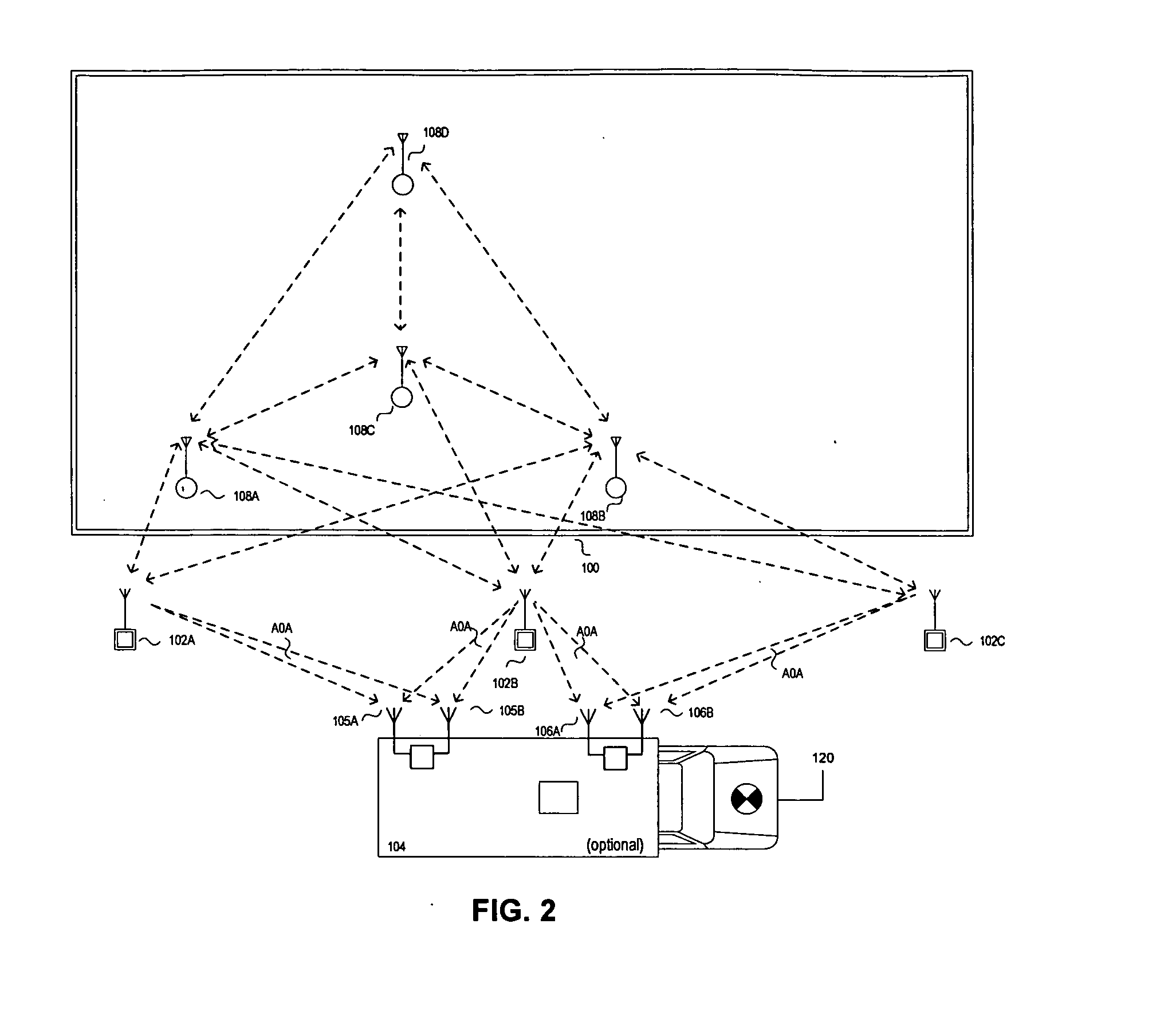
[0056] The invention is a novel position location system in a defined or ad-hoc wireless network distributed in and around a coverage area such as inside a structure. In the following description, numerous specific details are set forth in order to provide a thorough understanding of the present invention. In other instances, well known communication techniques have not been described in particular detail to avoid unnecessarily obscuring the invention. As herein defined, communications means transmission or reception of a signal with or without modulated information.

[0057] The present invention implements UWB radio communications technologies in a positioning architecture to improve the accuracy over known positioning systems and to further resolve positioning problems that are otherwise irresolvable, such as, but not limited to, providing a system for extensible positioning of non-fixed UWB radios (nodes).

[0058] An UWB radio provides a platform for solutions and improvements to c...


PUM


Abstract

A method and system for extensible positioning that uses a primary reference node at a known first position and a secondary reference node at a second position, where a range is measured between the secondary reference node and the primary reference node. The second position is determined based upon the first position and the measured range. A second range is measured between the secondary reference node and a non-fixed node. A third position corresponding to the non-fixed node is determined based upon the second position and the second range.

Description

CROSS-REFERENCE TO RELATED APPLICATIONS [0001] This application claims the benefit of U.S. Provisional Application Ser. No. 60 / 561,154, filed Apr. 12, 2004.GOVERNMENT RIGHTS [0002] The US Government has a paid-up license in this invention and the right in limited circumstances to require the patent owner to license others on reasonable terms as provided for by the terms of contract DDAB07-03-D-C213-0003 awarded by the United States Army Communications and Electronics Command, Fort Monmouth, N.J. 07703.FIELD OF THE INVENTION [0003] The present invention relates to positioning systems, and more particularly to ranging between two or more nodes having known positions and a fixed or non-fixed node to determine its position. BACKGROUND OF THE INVENTION [0004] Ultra wideband (UWB) positioning architectures are known to typically involve two or more reference radios used to determine the position of a target radio. Conventional UWB positioning architectures determine the position of the ta...

Claims


Application Information

Patent Timeline
Patent Type & Authority Applications(United States)
IPC IPC(8): G01S19/03G01S5/02G01S19/09G01S19/21G01S19/42G06F15/00
CPCG01S5/0289
Inventor FULLERTON, LARRY W.ROBERTS, MARK D.EINHORN, W. MICHAEL IILOUM, KELLYDODOUKH, IRINAO'HANIAN, S. SCOTT
Owner PLUS LOCATION SYST PTY
Why Eureka
Try Eureka