Angled toothed feed drum for hammermill

Inactive Publication Date: 2005-10-20
DIAMOND Z MFG
View PDF8 Cites 3 Cited by
  • Summary
  • Abstract
  • Description
  • Claims
  • Application Information

AI Technical Summary

Benefits of technology

[0011] Another feature of the device is that the rows of teeth can be arranged so that they are of different heights. For instance, every other, every third, or every fourth tooth, for insta

Problems solved by technology

A problem that can be encountered in feed rollers of the prior art is that they tend to feed material straight into the hammermill.
If a piece of wood is fed straight into the hammermill, two hammers of the hammermill may grind off the material, but material that passes in between the two hammer

Method used


Image

  • Angled toothed feed drum for hammermill
  • Angled toothed feed drum for hammermill
  • Angled toothed feed drum for hammermill

Examples


Example

[0021] While the invention is susceptible of various modifications and alternative constructions, certain illustrated embodiments thereof have been shown in the drawings and will be described below in detail. It should be understood, however, that there is no intention to limit the invention to the specific form disclosed, but, on the contrary, the invention is to cover all modifications, alternative constructions, and equivalents falling within the spirit and scope of the invention as defined in the claims.

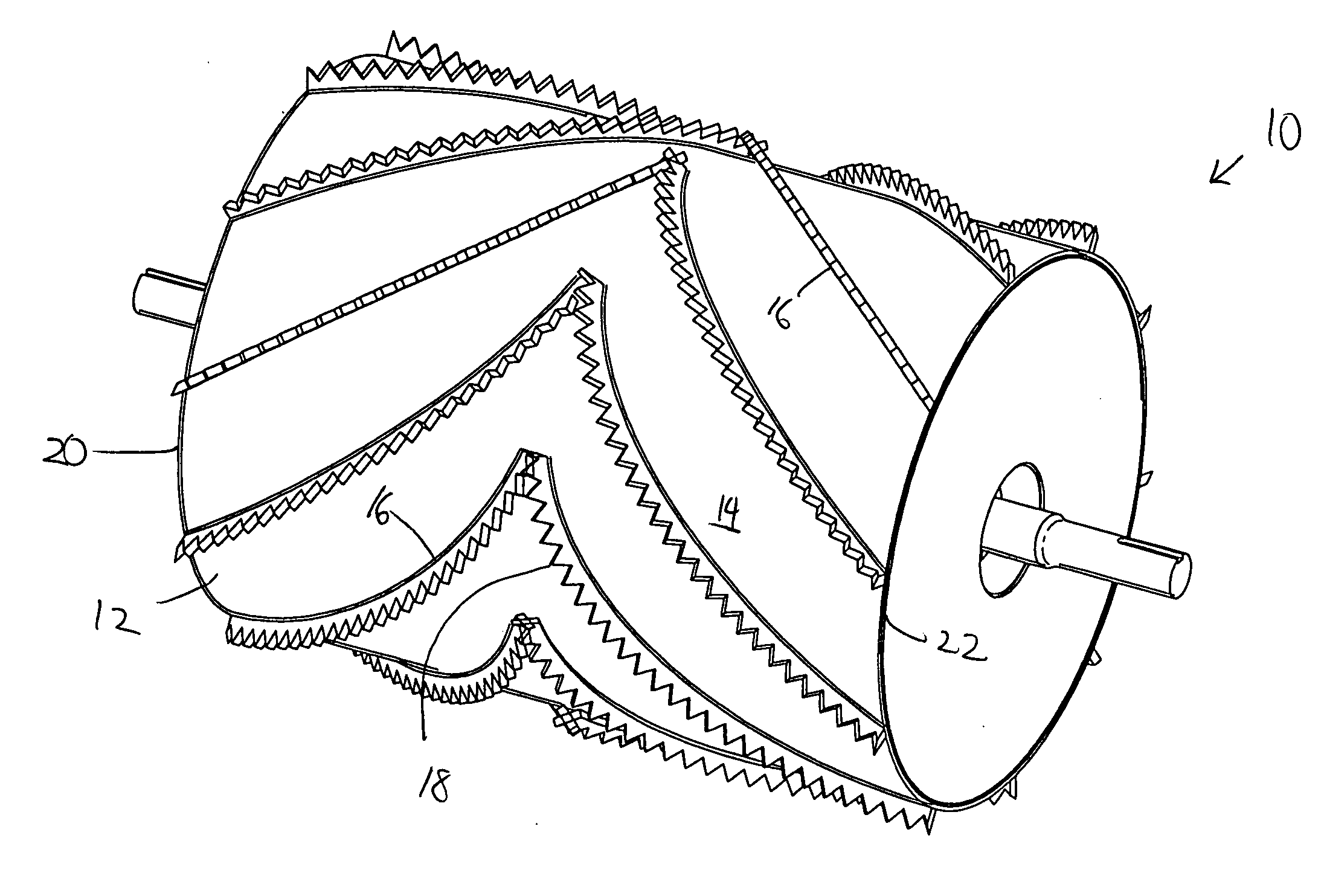
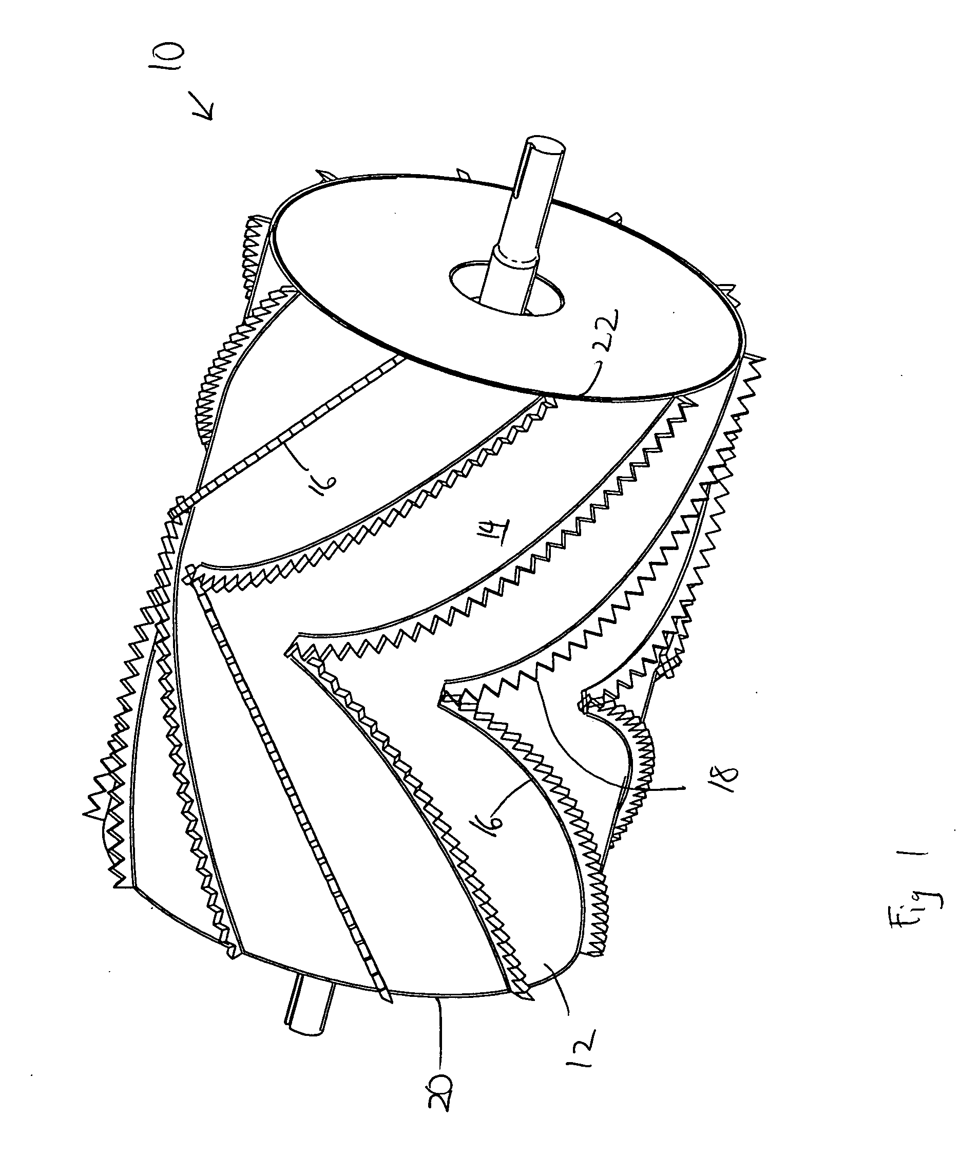
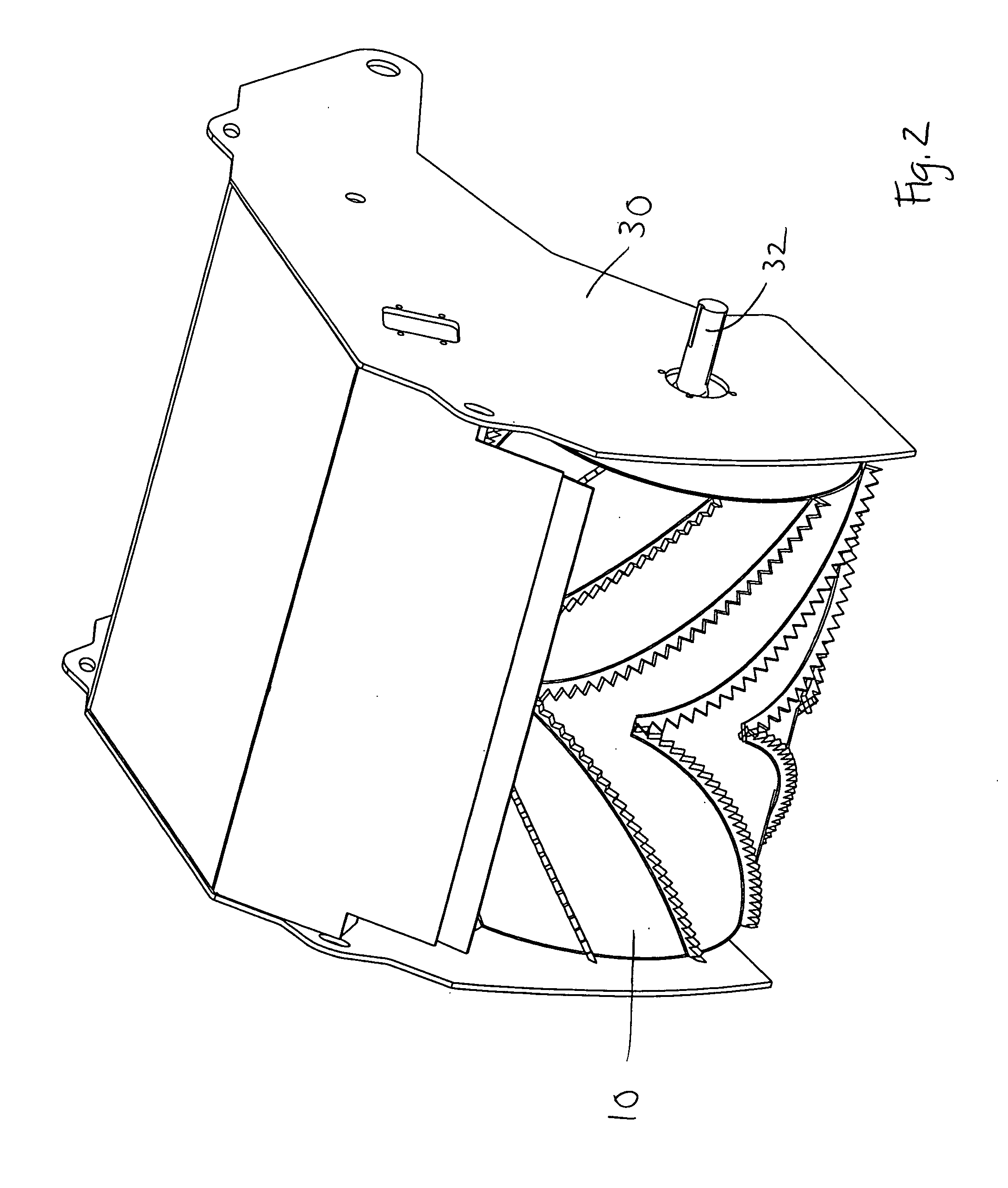
[0022] Some preferred embodiments of the preferred embodiment are shown in FIGS. 1 through 7. FIG. 1 shows a perspective view of the feed roller of the present invention. As used herein, “radial” and “radially” refer to directions perpendicular to the axis of rotation, or the longitudinal axis of the cylinder; and “axial” and “axially” refer to directions parallel to the axis of rotation of the cylinder. The feed roller device of the present invention is designated as 10 in the ...


PUM


Abstract

The present invention includes a feed roller for hammermills that includes teeth arranged in rows at an angle with alternating larger and smaller teeth. This arrangement of rows of teeth and larger/smaller teeth on the feed roller of a hammermill increases the grip of the feed roller on the material and intends to move material from the lateral edges towards the center of the hammermill. This is advantageous for grinding, as some lateral motion upon feeding material into the hammermill is desirable.

Description

BACKGROUND OF THE INVENTION [0001] 1. Field of the Invention [0002] The present invention generally relates to hammermills, and more particularly relates to feed rollers of horizontal hammermills. [0003] 2. Background Information [0004] One type of hammermill is a horizontal hammermill. A horizontal hammermill has a rotating hammermill with heavy hammers that break apart the material being shredded. Material being fed into the hammermill is typically fed in on a chain. A common feature on horizontal hammermills is a powered cylindrical drum called a feed roller, which is a large cylindrical structure that presses down against the feed belt. This serves to grip material that is on the feed belt and hold it in place as it is fed into the hammermill. [0005] Some type of gripping surface is provided on the feed roller in order to better grip the material being fed into the hammermill. The gripping structure(s) can be teeth, ridges or rails. The typical orientation of such teeth is to ha...

Claims


Application Information

Patent Timeline
IPC IPC(8): B02C13/286B02C18/22
CPCB02C13/286B02C2013/28645B02C18/225
Inventor BONNER, CARL
Owner DIAMOND Z MFG
Why Eureka
Try Eureka