Payload fairing separation system

a technology for separation systems and payload fairings, which is applied in the direction of transportation and packaging, cosmonautic vehicles, aircrafts, etc., can solve the problems of significant force insertion by the mechanism on the interlock, and achieve the effects of convenient transportation, improved reliability, and less expensive work

Inactive Publication Date: 2005-10-20
BUEHLER DAVID BENJAMIN
View PDF0 Cites 31 Cited by
  • Summary
  • Abstract
  • Description
  • Claims
  • Application Information

AI Technical Summary

Benefits of technology

[0028] During the time the vehicle is traveling through the atmosphere, the payload fairing is used to shield the payload from aerodynamic forces. Once the vehicle has left the atmosphere, the payload fairing may be jettisoned to minimize the extra mass the vehicle is carrying.
[0029] By using a combination of point connection devices and seam connectors, the seam connectors can be built so that they do not have to release instantaneously. For example, the disengagement mechanism for the seam connectors could consist of a motor driving a gear reduction system. With proper gearing, such a disengagement mechanism can insert a significant amount of force on the interlock, with only a modest continuous power input.
[0033] This separation system has several advantages. It can be transported easily. It is less expensive to work with because it has no explosives. The mechanism can be tested repeatedly, and the same mechanism flies. This should improve reliability. It can be activated to easily disassemble the fairing, and then easily reset. It can also be sealed at the customer's site and filled with inert gas, then transported to the launch facility and launched. This reduces operation costs by not requiring a clean room at the launch facility. It also has the advantage that it releases gently, with no high shock loads to the payload.

Problems solved by technology

With proper gearing, such a disengagement mechanism can insert a significant amount of force on the interlock, with only a modest continuous power input.

Method used


Image

  • Payload fairing separation system
  • Payload fairing separation system
  • Payload fairing separation system

Examples


Embodiment Construction

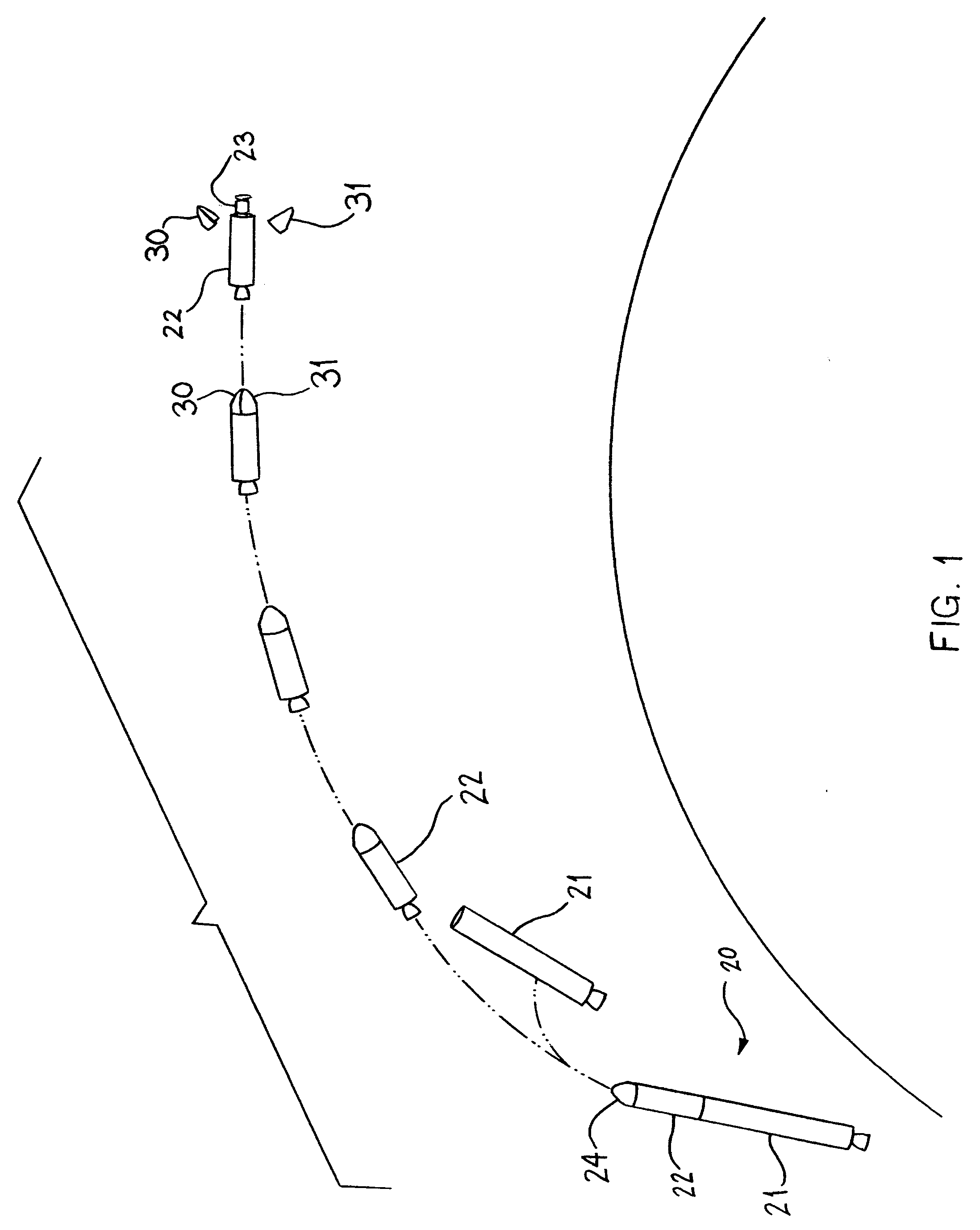
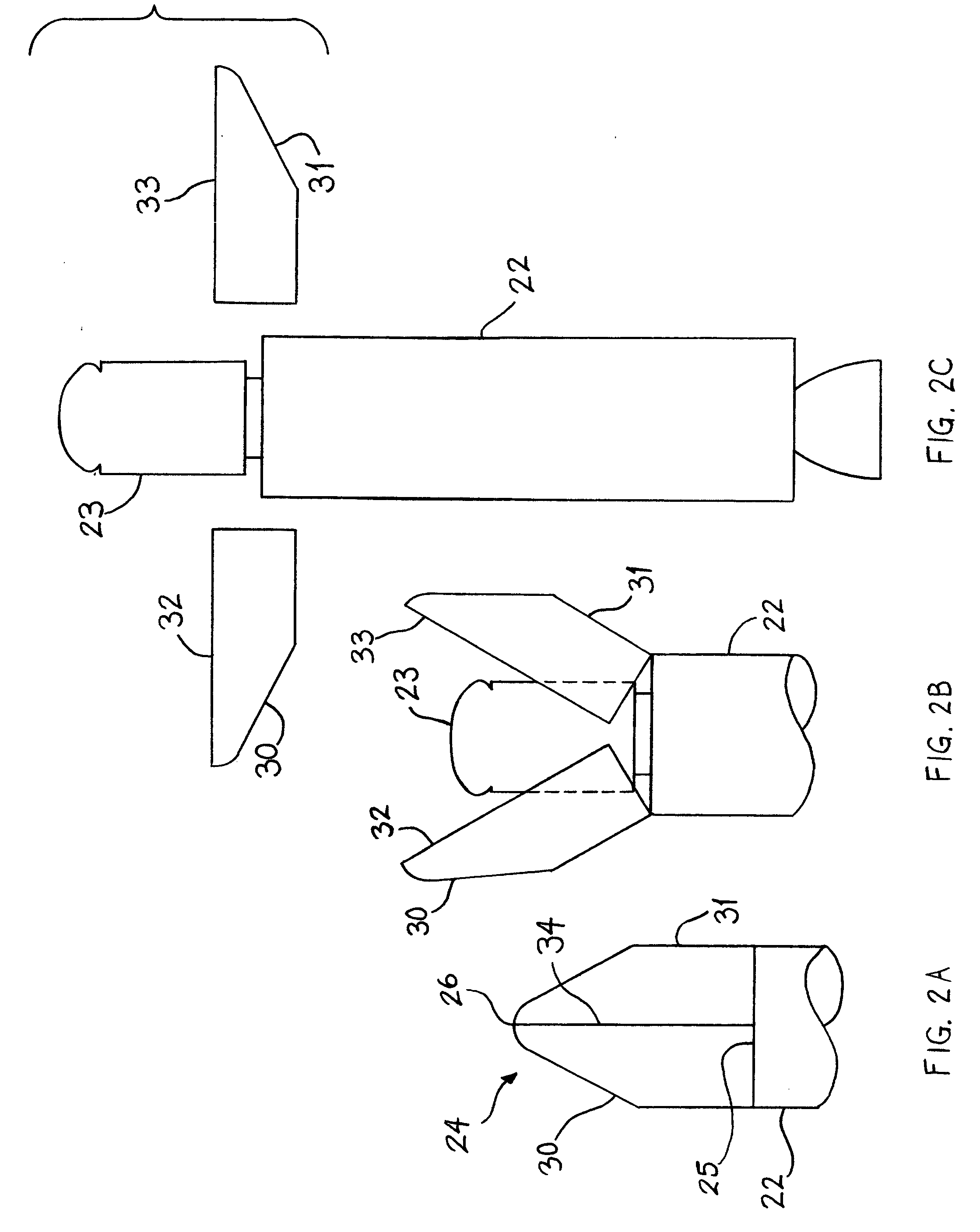
[0042] Referring to FIGS. 1-2, the typical launch vehicle, generally indicated by numeral 20, includes a lower stage 21 and upper stage 22 upon which is mounted a payload 23 covered by a fairing assembly 24. The fairing assembly 24 is generally cone shaped having a base portion 25 and a nose end 26. Typically two or more stages are necessary to place a satellite in orbit.

[0043] Referring to FIG. 2A to 2C, the fairing comprises two fairing halves 30 and 31 having mating edges 32 and 33 that meet to form a seam 34.

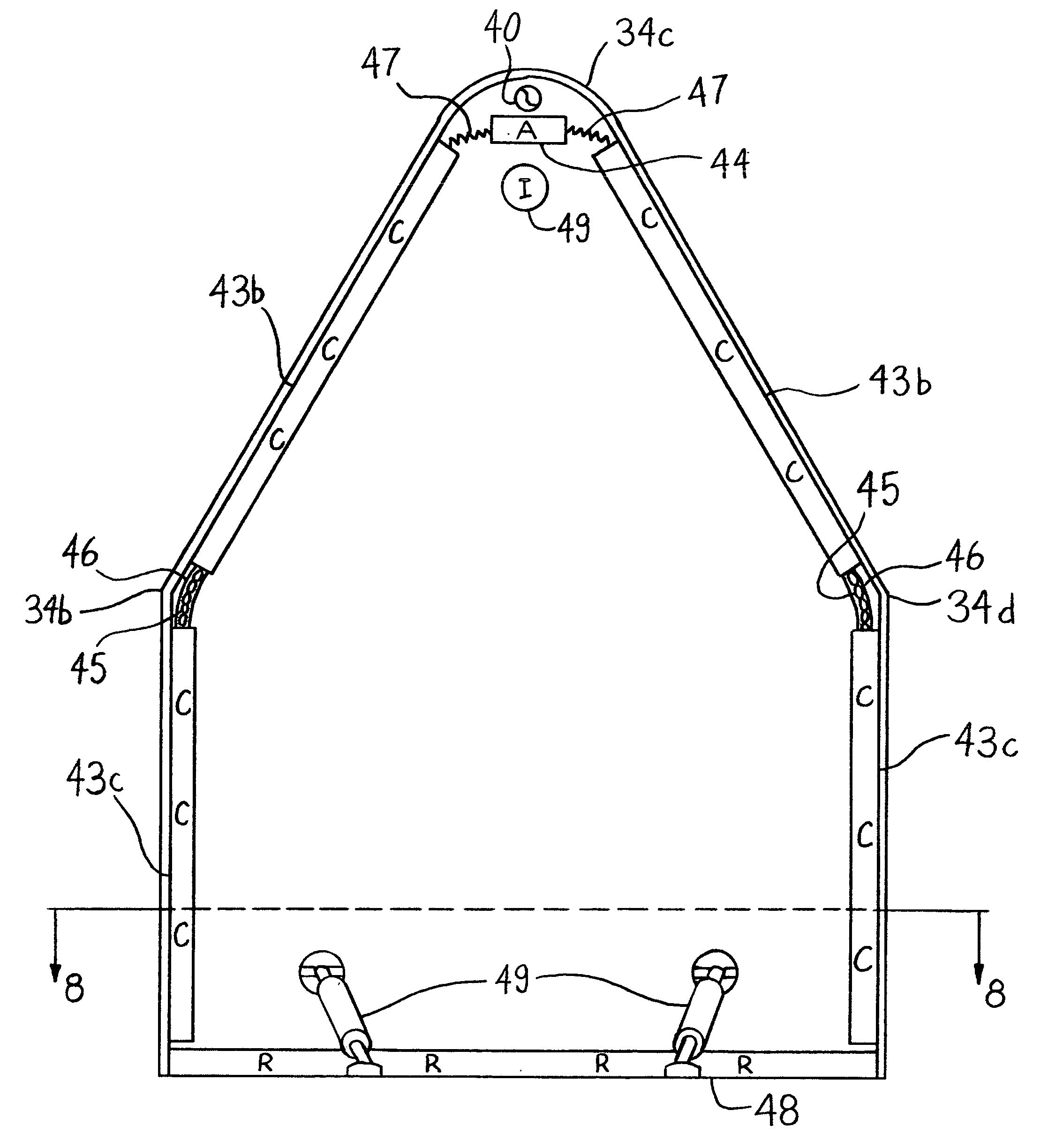
[0044] Referring to FIG. 3, at the nose 26 the mating edges of the fairing halves 30 and 31 are articulated so as to be joinable by a releasable point connector 40, represented in FIGS. 3 and 6A to 7C by a circle inscribed with an S-curve. The releasable point connector 40 also may take a variety of forms, including the Starsys FASSN. Mounted on the interior surfaces 41 and 42 of the fairing halves 30 and 31 are a plurality of resettable, releasable seam connectors 43, eac...


PUM


Abstract

The invention is a payload fairing separation system that is resettable and operates in two stages. The system includes releasable, resettable seam connectors that hold the fairing together in combination with releasable point connectors. At the time of separation, the seam connectors release first, and then the point connectors release. This allows the fairing to separate cleanly at a precise time, without using pyrotechnic charges, and with low shock to the payload.

Description

[0001] This application is a continuation of provisional application No. 60 / 477,536 filed on Jun. 11, 2003, titled “Two-stage, resettable, non-pyrotechnic payload separation system”.BACKGROUND OF THE INVENTION [0002] The invention relates to the field of separation systems for orbital launch vehicle payload fairings and the like and, in particular, to a separation system that does not include pyrotechnics. [0003] Description Of Related Art [0004] Payload fairings are used to protect the spacecraft or other payload while it is being transported into orbit on a rocket. Without a fairing, the spacecraft atop the rocket would be subjected to large aerodynamic loads. The fairing blocks the aerodynamic loads, and transmits forces down to the rocket. [0005] Once the rocket has left the atmosphere, the payload fairing is typically jettisoned. It is preferably jettisoned before the rocket reaches orbit, in order to reduce the amount of mass the rocket must launch into orbit. If the payload f...

Claims


Application Information

Patent Timeline
Patent Type & Authority Applications(United States)
IPC IPC(8): B64G1/52B64G1/64
CPCB64G1/645
Inventor BUEHLER, DAVID BENJAMIN
Owner BUEHLER DAVID BENJAMIN
Why Eureka
Try Eureka