Low-voltage bandgap voltage reference circuit

a low-voltage bandgap voltage and reference circuit technology, applied in the direction of electric variable regulation, process and machine control, instruments, etc., can solve the problems of increasing power consumption, difficulty in further reducing supply and reference voltages, and undetectable consumption of large amounts of real estate on integrated circuit chips

Inactive Publication Date: 2005-10-20
RAUM TECH CORP
View PDF16 Cites 59 Cited by
  • Summary
  • Abstract
  • Description
  • Claims
  • Application Information

AI Technical Summary

Benefits of technology

[0012] An advantage of the present invention is that a reference voltage of less than approximately 1.2 Volts is generated without the disadvantages of the fractional VBE approach.

Problems solved by technology

However, it is difficult to further reduce supply and reference voltages since typical bandgap voltage reference circuits provide a minimum reference voltage VREF of about 1.2 to 1.3 V and therefore require a supply voltage of at least approximately 1.4 V (one drain-source voltage drop higher than the reference voltage).
The bandgap voltage reference circuits that use the fractional VBE approach, however, require additional voltage-dividing circuitry, such as resistors, that undesirably consume relatively large amounts of real estate on integrated circuit chips and raise power consumption.

Method used


Image

  • Low-voltage bandgap voltage reference circuit
  • Low-voltage bandgap voltage reference circuit
  • Low-voltage bandgap voltage reference circuit

Examples


Embodiment Construction

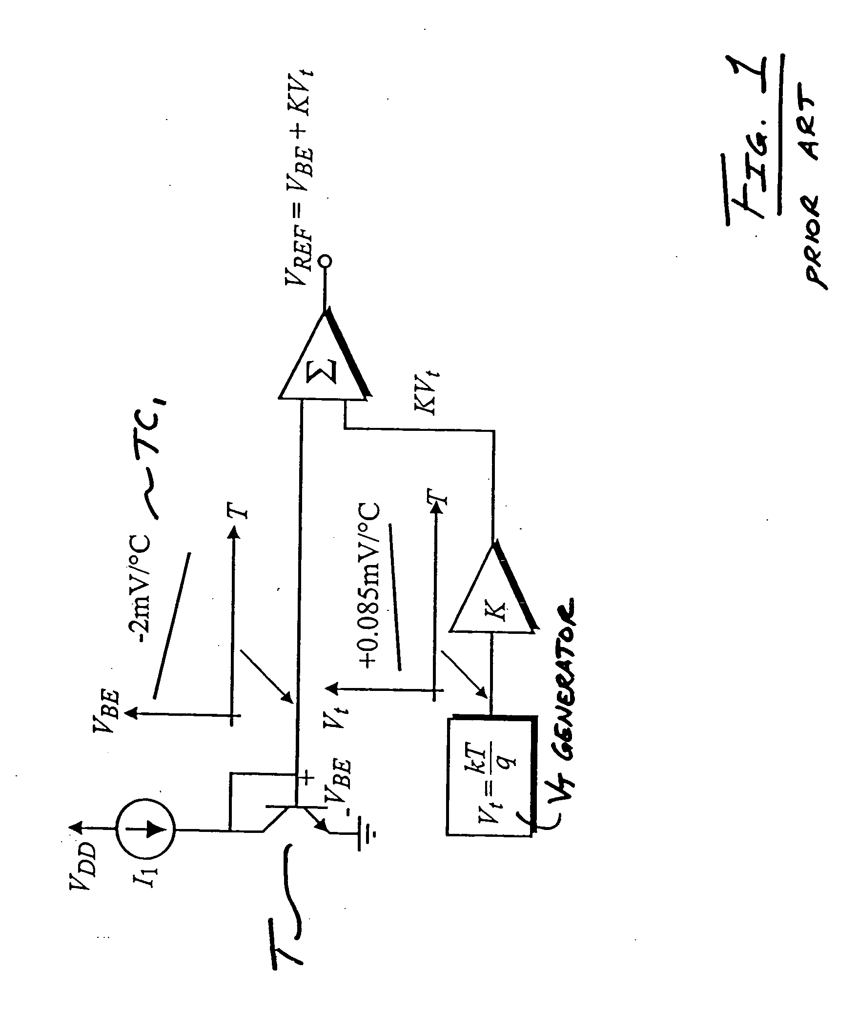
[0021] Referring now to the drawings and particularly to FIG. 1, a block diagram that illustrates the operational principles of a conventional bandgap voltage reference circuit is shown. Transistor T has a base-to-emitter voltage VBE with a typical temperature coefficient (TC) of approximately negative 2 millivolts (mV) per degree Celsius, shown in plot TC1. The VBE TC produces a VBE voltage that is CTAT. Thermal voltage Vt is generated by Vt generator and is scaled by scaling factor K. Thermal voltage Vt has a TC of approximately +0.085 mV per degree Celsius, which is scaled by scaling factor K to a TC of approximately +2 mV per degree Celsius. Scaled thermal voltage KVt is PTAT and similar in magnitude to VBE. Thus, when VBE and scaled thermal voltage KVt are summed by summing circuit Σ their TC's cancel each other and a temperature-stable reference voltage VREF of approximately 1.2 to 1.3 V results.

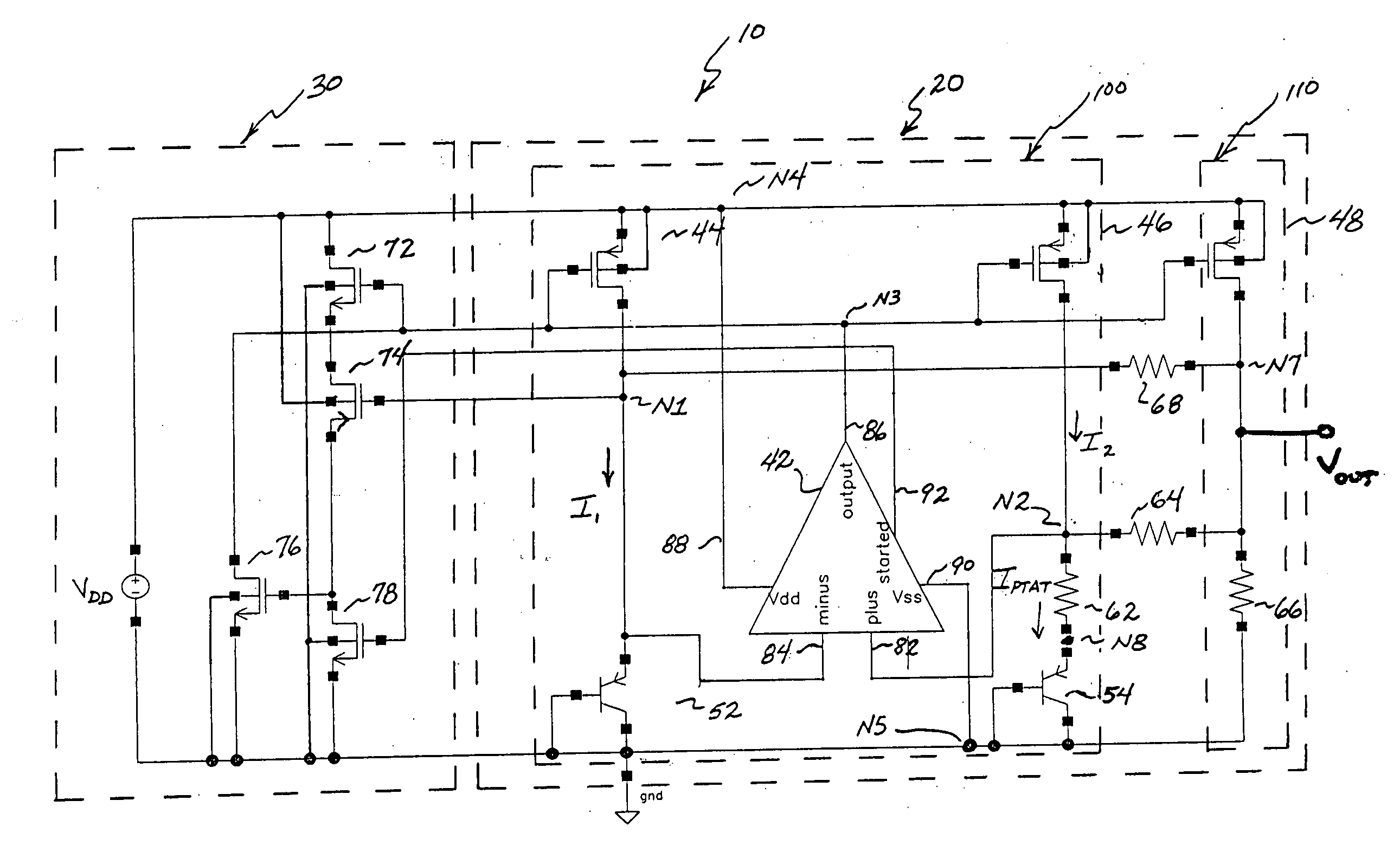
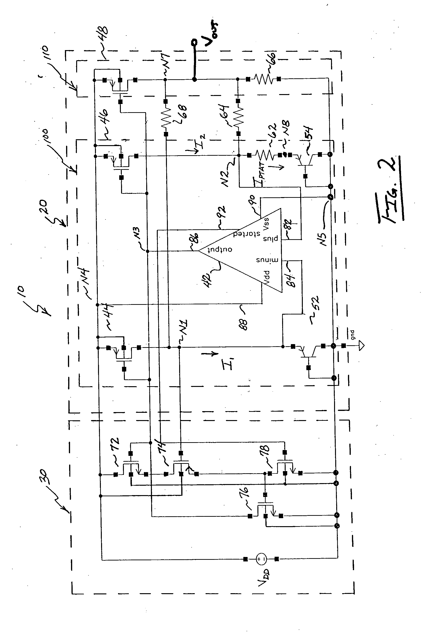
[0022] In contrast to the operational principles of conventional bandgap voltage ...


PUM


Abstract

A bandgap reference voltage generating circuit includes a proportional to absolute temperature (PTAT) voltage generating means generating a PTAT voltage. A complementary to absolute temperature (CTAT) voltage generating means generates a CTAT voltage. A temperature coefficient determining means interconnects the PTAT voltage generating means and the CTAT voltage generating means.

Description

CROSS-REFERENCE TO RELATED APPLICATIONS [0001] This application claims the benefit of U.S. Provisional Patent Application No. 60 / 562,843, filed 16 Apr. 2004.TECHNICAL FIELD [0002] The present invention relates to bandgap voltage reference circuits. BACKGROUND [0003] Bandgap voltage reference circuits generate a reference voltage that is relatively stable over a wide temperature range by balancing a voltage having a negative temperature coefficient (TC) and which is thus complementary to absolute temperature (CTAT) with a voltage having a positive temperature coefficient (TC) and which is thus proportional to absolute temperature (PTAT). Typically, the forward-biased p-n junction of a diode or the forward-biased base-to-emitter junction of a transistor provides the CTAT voltage, and the thermal voltage of a diode or transistor provides the PTAT voltage. Generally, the two voltages are scaled or voltage-divided as necessary and summed to produce the temperature-stable reference voltag...

Claims


Application Information

Patent Timeline
Patent Type & Authority Applications(United States)
IPC IPC(8): G05F1/10G05F3/30
CPCG05F3/30
Inventor WASHBURN, CLYDE
Owner RAUM TECH CORP
Why Eureka
Try Eureka