Computed tomography unit having an aperture stop

a tomography unit and aperture stop technology, applied in the field of tomography units, can solve the problems of unfavorable, enlarged dead spaces between active radiation areas, and the problem of avoiding the problem, so as to improve the resolution and increase the radiation dose

Active Publication Date: 2005-10-20
SIEMENS HEALTHCARE GMBH
View PDF7 Cites 7 Cited by
  • Summary
  • Abstract
  • Description
  • Claims
  • Application Information

AI Technical Summary

Benefits of technology

[0005] It is an object of an embodiment of the invention to find a computed tomography unit having a multirow detector and which has an improved resolution, without the need to increase the radiation dose used.

Problems solved by technology

The inventors have realized that an increase in the longitudinal resolution, that is to say the resolution in the direction of the z-axis or the system axis, both undesirably increases the required radiation dose, and leads to an enlargement, likewise undesired, of the dead spaces between the active radiation areas.
This problem can, however, be circumvented when the scanning rate is raised.

Method used


Image

  • Computed tomography unit having an aperture stop
  • Computed tomography unit having an aperture stop
  • Computed tomography unit having an aperture stop

Examples


Embodiment Construction

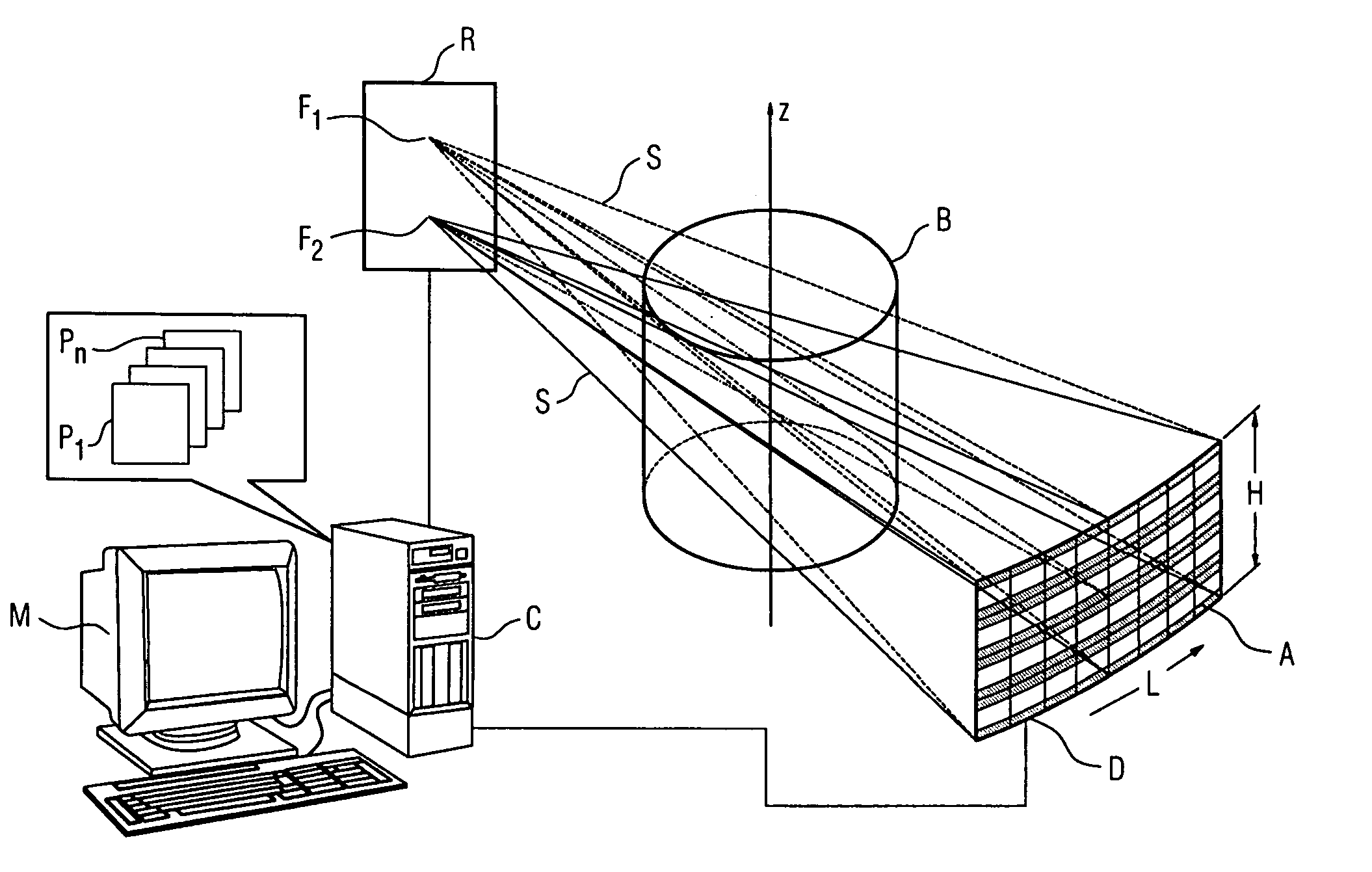
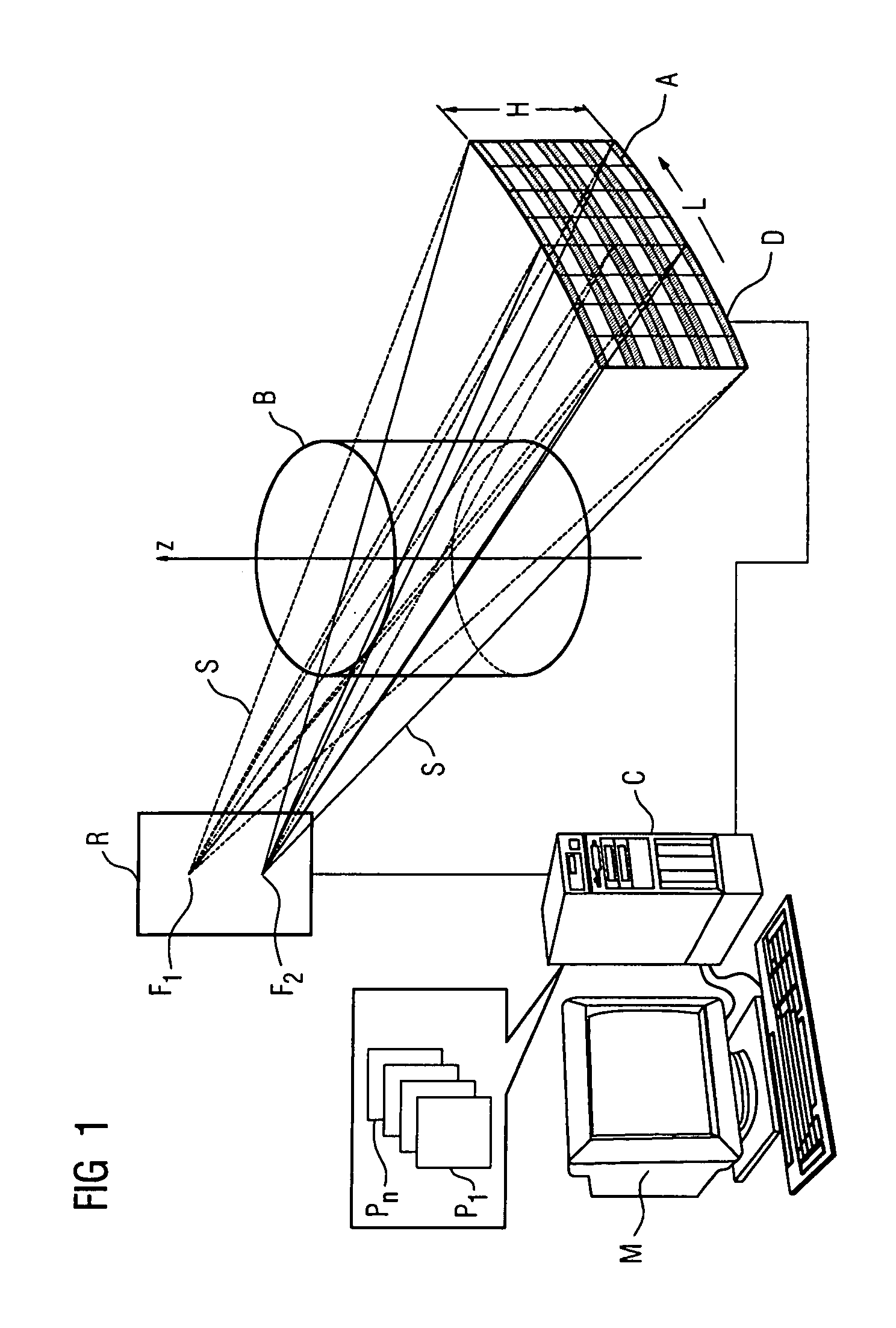
[0019]FIG. 1 shows a schematic of a computed tomography unit according to an embodiment of the invention and having a flying focus with two flying focus positions F1 and F2 that in each case emit beams S onto a detector D and in the process penetrate an examination object B, the attenuation of their radiation being measured by the detector D. The detector D has a length L in the circumferential direction and a width H in the z-direction and is divided into a multiplicity of detector rows that consist, in turn, of individual detector elements, there being placed over the individual detector rows, in the example shown, an aperture stop that acts exclusively in the z-direction. The control of the focus positions and the picking up of the data from the detector are performed via a computer unit C that has appropriate programs Pn for control including driving the flying focus positions, data pickup for the detector, data conditioning to form the CT image and for carrying out the method a...


PUM

PropertyMeasurementUnit
computed tomographyaaaaaaaaaa
spatial frequency faaaaaaaaaa
Nyquist frequencyaaaaaaaaaa

Abstract

A computed tomography unit includes at least one X-ray tube, that scans an object in a fashion rotating in a circle or spiral about a z-axis, in combination with an oppositely situated detector having a multiplicity of detector rows. Each detector row includes an aperture Δz in the z-direction, having a multiplicity of detector elements. Between the X-ray tube and detector, a detector diaphragm is arranged that reduces the aperture Δz of the detector rows in the z-direction. The X-ray tube includes a focus, of variable location relative to the X-ray tube and which alternatingly assumes during scanning at least two different positions that have different z-coordinates relative to the X-ray tube R.

Description

[0001] The present application hereby claims priority under 35 U.S.C. §119 on German patent application number DE 10 2004 017 538.1 filed Apr. 8, 2004, the entire contents of which is hereby incorporated herein by reference. FIELD OF THE INVENTION [0002] The invention generally relates to a computed tomography unit having at least one X-ray tube. Preferably it relates to such a unit which scans an object, in a fashion rotating in a circle or spiral about a z-axis, in combination with an oppositely situated detector having a multiplicity of detector rows. Each detector row may include an aperture Δz in the z-direction, having a multiplicity of detector elements. Furthermore, being arranged between the X-ray tube and detector, there may be a detector diaphragm that reduces the aperture Δz of the detector rows in the z-direction. BACKGROUND OF THE INVENTION [0003] German laid-open patent application DE 102 11 948 A1 has disclosed a computed tomography unit that is equipped with an X-ra...

Claims


Application Information

Patent Timeline
Patent Type & Authority Applications(United States)
IPC IPC(8): A61B6/00A61B6/03G01N23/00G01N23/04G21K1/02G21K1/12H05G1/60
CPCA61B6/032A61B6/4028G01N2223/419G01N23/046A61B6/4085
Inventor BRUDER, HERBERTFLOHR, THOMASSTIERSTORFER, KARL
Owner SIEMENS HEALTHCARE GMBH
Why Eureka
Try Eureka