Roll paper holding mechanism and printer

a technology of holding mechanism and rolling paper, which is applied in the direction of printing, thin material processing, other printing apparatuses, etc., can solve the problems of reducing the weight of the roll paper, increasing production costs, and causing the roll paper to overrun, so as to avoid the increase of the cost of the driving unit, the effect of stably operating and effective prevention of the overrun of the roll paper

Inactive Publication Date: 2005-10-20
STAR MICRONICS
View PDF0 Cites 26 Cited by
  • Summary
  • Abstract
  • Description
  • Claims
  • Application Information

AI Technical Summary

Benefits of technology

[0018] The invention is characterized in that the pressing force of the pressing unit which presses the side face of roll paper held by the holding unit is gradually reduced by the pressing force adjusting section in accordance with reduction of the diameter of the roll paper. According to the configuration, first, overrun of the roll paper by an inertia force can be effectively prevented by the pressing unit from occurring. Moreover, irrespective of the outer diameter and weight of the roll paper which vary in accordance with consumption, paper can be pulled out by a driving force that is constant or substantially constant. As a result, the driving unit can stably operate, and increase of the cost of the driving unit can be avoided.

Problems solved by technology

When the diameter of the roll paper is considerably reduced, therefore, the load of the motor for pulling out the paper is excessively increased, thereby causing a possibility that a failure such as step out occurs.
In this case, however, the production cost is increased.
When consumption of the paper is advanced and the weight of the roll paper is reduced, however, the whole roll paper is pulled by the operation of pulling out the paper to be raised, and the raised state is held by the elastic member, so that the roll paper is hardly returned by its own weight to the bottom portion of the housing space.
In the case where a sensor which detects that the paper amount is reduced and informs of the reduction in order to promote replacement of the paper is disposed on the side face of the roll paper, the sensor may malfunction because the roll paper does not exist at a predetermined position.

Method used


Image

  • Roll paper holding mechanism and printer
  • Roll paper holding mechanism and printer
  • Roll paper holding mechanism and printer

Examples


first embodiment

(1) First Embodiment

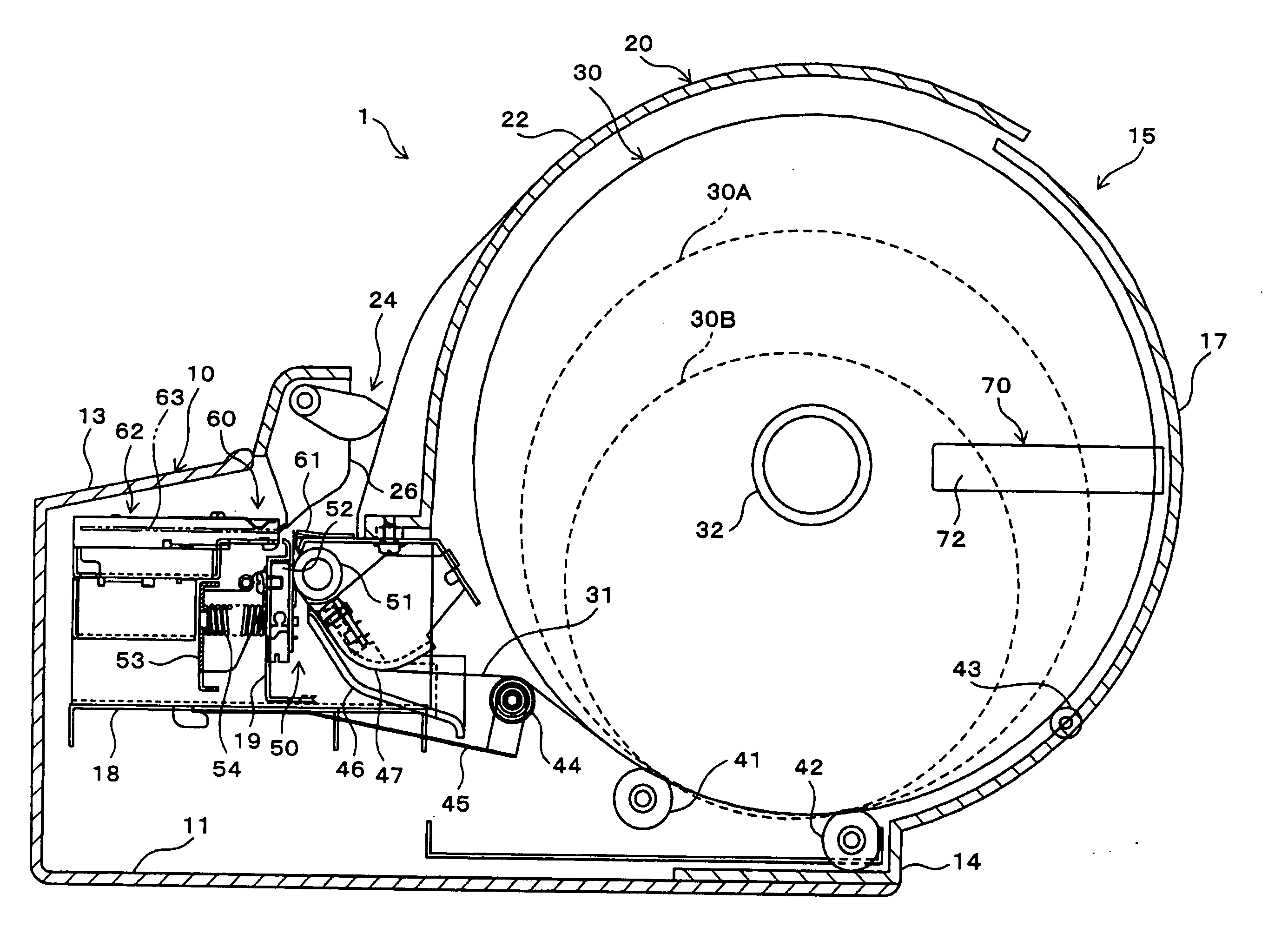
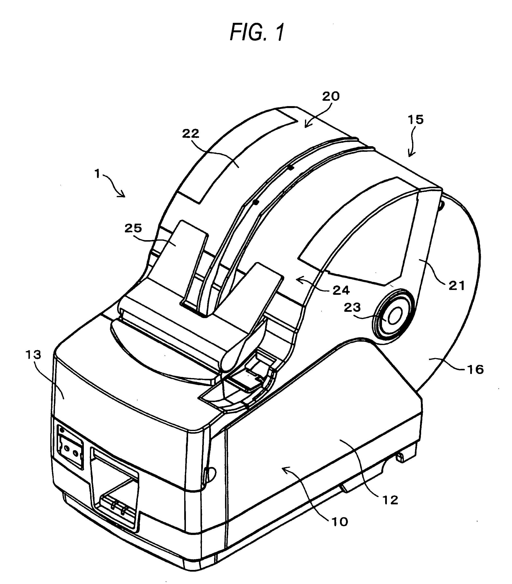
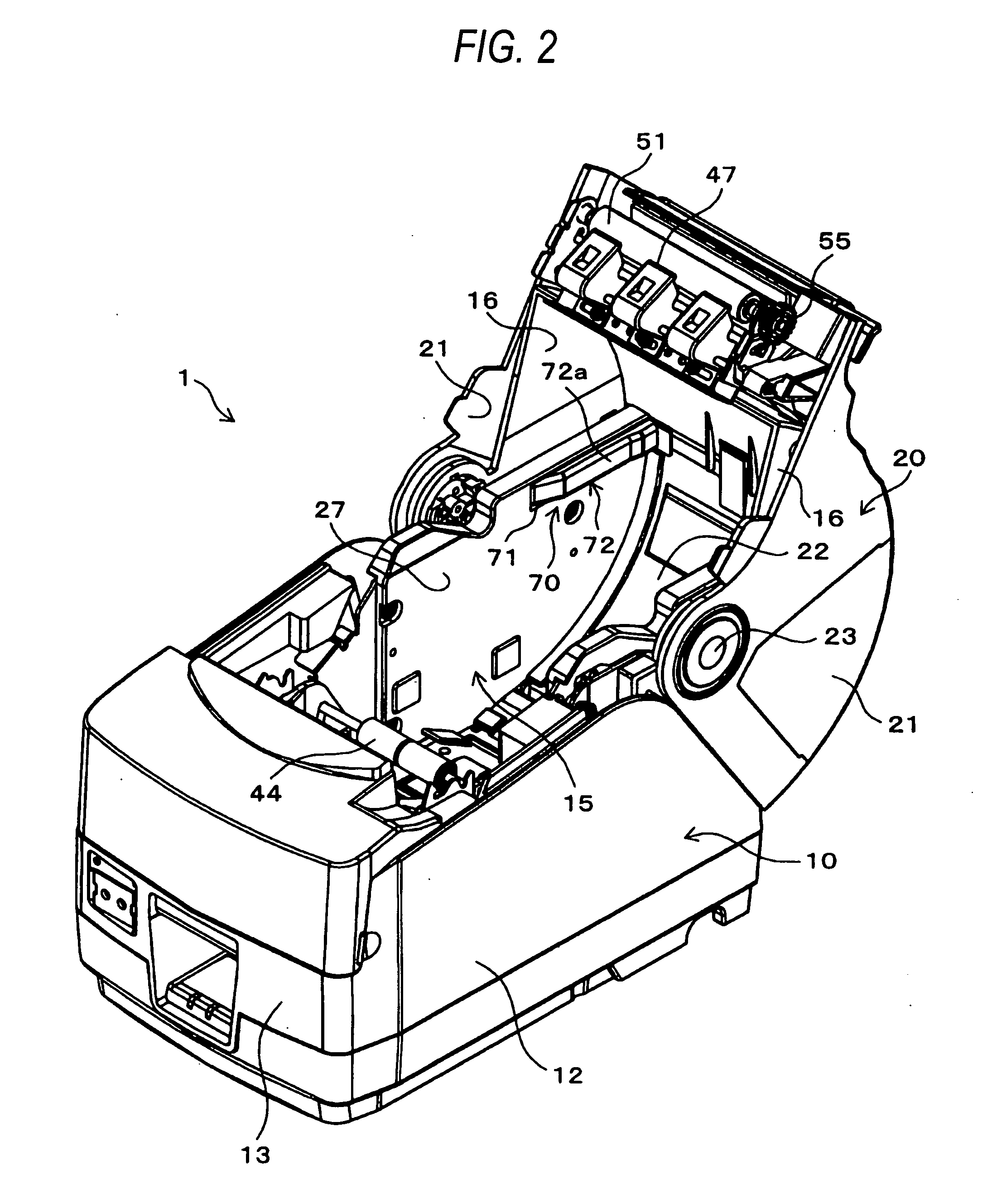
[0029]FIG. 1 shows a small printer which is preferably used in an electronic cash register or the like. In a printer 1, the external shape is formed by an outer case 10 and a cover 20 which is openably attached to the outer case 10. FIG. 1 is a perspective view showing a state where the cover 20 is closed, and FIG. 2 is a perspective view showing a state where the cover 20 is opened. FIG. 3 is a side sectional view showing the state where the cover 20 is closed.

[0030] As shown in FIGS. 1 to 3, the outer case 10 has a box-like shape including a bottom plate 11, a pair of right and left side plates 12, a front plate 13, and a back plate 14. A roll paper holder unit (holding unit) 15 which has a substantially semi cylindrical shape is formed in rear of the case. The roll paper holder unit 15 is of the drop-in type in which a roll paper 30 is dropped to be loaded, and formed by: right and left rear plates 16 which have a substantially sector shape, and which are for...

second embodiment

(2) Second Embodiment

[0057] Next, a pressing unit 80 in a second embodiment which is another mode of the pressing unit 70 in the first embodiment will be described with reference to FIGS. 5(a) to 5(d).

[0058] In FIG. 5(a), 82 denotes pressing plates (pressing members) constituting the pressing unit 80 in the second embodiment. Each of the pressing plates 82 is configured in a similar manner as the pressing plate 72 in the first embodiment, but the claw 73 in the front-end portion is not formed, and the front-end portion and the claw 74 in the rear-end portion are not inserted into the cutaway 71 of the inner plate 27. In the embodiment, a rectangular plate spring 83 which longitudinally elongates is disposed in place of the spring seat plate 75 and the two coil springs 76, 77 in the first embodiment.

[0059] In the plate spring 83, a front-end portion which is an end portion in the direction of the length is cantilevered to the outer face of the inner plate 27 which is more forward t...

third embodiment

(3) Third Embodiment

[0063] FIGS. 6, 7(a) and 7(b) are diagrams schematically showing a third embodiment in which the side faces of the roll paper 30 are pressed with using the own weight of the roll paper 30. In the embodiment, a roll paper holder unit (holding unit) 90 is of the drop-in type, and configured by a pair of right and left pressing plates (pressing members) 92. The pressing plates 92 have a rectangular shape which is longer than the maximum diameter of the roll paper 30, and are incorporated so as to, in a state where the roll paper 30 is loaded, vertically extend and oppose each other in parallel so as to hold the roll paper 30 therebetween.

[0064] In each of the pressing plates 92, a bearing 92a is formed on the outer face of an end portion (the lower portion in FIGS. 6, 7(a) and 7(b)), and a support shaft 93 which horizontally elongates is passed through the bearing 92a. The support shafts 93 are fixed to the frame (not shown) or the like of the printer so as to be p...


PUM


Abstract

Pressing plates press side faces of a roll paper loaded into a roll paper holder unit of the drop-in type, thereby preventing overrun of the roll paper caused by an inertia force from occurring. Each of the pressing plates is urged by two coil springs which are placed respectively on inner and outer circumference sides of the roll paper. The coil spring on the outer circumference side has a higher elasticity than the coil spring on the inner circumference side. According to the configuration, the pressing force of the pressing plates due to the elasticity of the coil springs is gradually reduced in accordance with reduction of a diameter of the roll paper.

Description

BACKGROUND OF THE INVENTION [0001] 1. Field of the Invention [0002] The present invention relates to a roll paper holding mechanism which rotatably holds a roll paper at a predetermined position, the roll paper being rotated by pulling out a leading portion of the paper, and more particularly to a roll paper holding mechanism having a structure which presses a side face of a roll paper. The invention relates also to a printer including such a roll paper holding mechanism. [0003] 2. Description of the Related Art [0004] In small printers and the like, such a roll paper is often used. The roll paper is rotatably held by a structure of the drop-in type in which the roll paper is dropped in a housing space, or of the shaft-supporting type in which a core member is supported by a shaft, and then the paper is pulled out by a motor to be subjected to a printing process. When the paper is pulled out in order to conduct a printing process, the roll paper is rotated. Even when the printing pr...

Claims


Application Information

Patent Timeline
Patent Type & Authority Applications(United States)
IPC IPC(8): B41J15/16B41J15/04B65H16/02
CPCB41J15/16B41J15/042
Inventor OGAWA, TAKESHIMOCHIZUKI, YASUFUMIMASUDA, YUJI
Owner STAR MICRONICS
Why Eureka
Try Eureka