Variable radius continuously variable transmission

a continuously variable transmission and variable radius technology, applied in the field of transmissions, to achieve the effect of reducing the cost of mass production, and reducing the number of strokes

Inactive Publication Date: 2005-10-20
GREEN ARTHUR G +2
View PDF10 Cites 61 Cited by
  • Summary
  • Abstract
  • Description
  • Claims
  • Application Information

AI Technical Summary

Benefits of technology

[0016] 1. An object of this invention is to provide a multi-purpose highly efficient chain or belt drive continuously variable transmission with minimal losses between input and output energy.
[0017] 2. Another object of this invention is to provide a highly efficient bicycle transmission with minimized frictional losses to transfer pedal power to drive wheel more efficiently than multiple-sprocket / derailleur transmissions even in non-shifting mode.
[0018] 3. Another object of this invention is to provide a bicycle transmission which transfers pedal power to drive wheel without significant loss of power during shifting, i.e. more efficiently than multiple-sprocket / derailleur and other existing bicycle transmissions.

Problems solved by technology

The fundamental previously unsolved problem of variable radius chain or cog belt transmissions is how to alter the radius of the drive or driven sprocket wheel without binding or breaking (or stretching or bunching up) the chain or cogbelt.

Method used


Image

  • Variable radius continuously variable transmission
  • Variable radius continuously variable transmission
  • Variable radius continuously variable transmission

Examples


Embodiment Construction

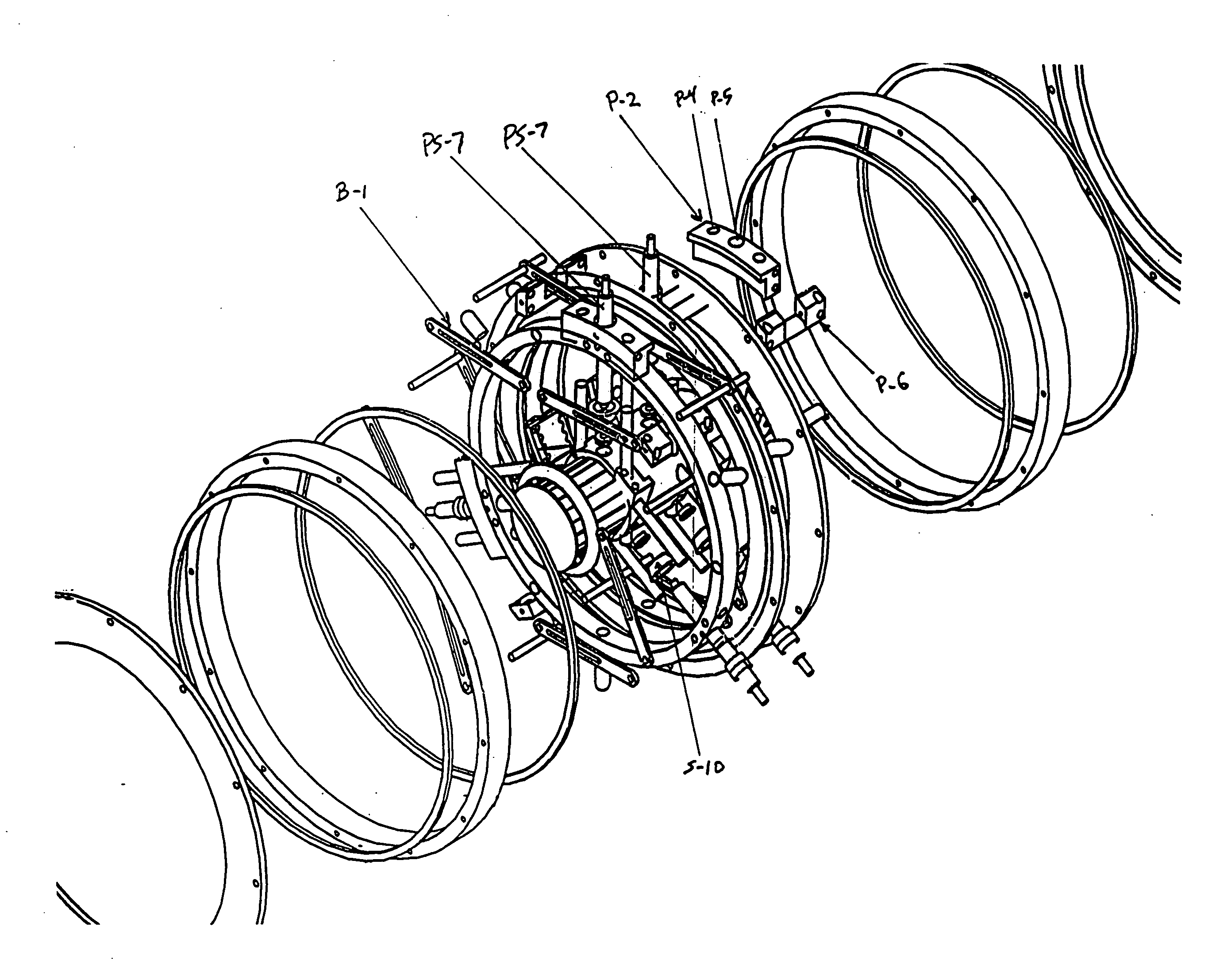
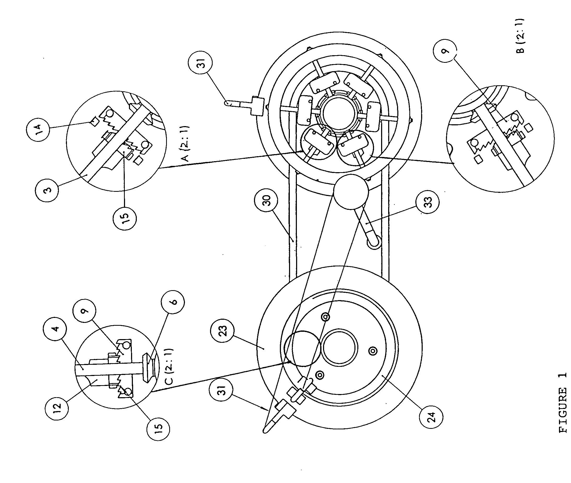
[0111]FIG. 1 presents a schematic side view of two drives of the continuously variable transmission in a preferred embodiment together with a circuit in form of a chain 30, depicting a bicycle set to move from left to right as viewed, with the transmission in a preferred embodiment. A pedal 34 shown on the drive at the right of the figure indicates that it is the input drive, or driver; the drive to the left of the view is the follower. The two drives are identical but we view their opposite sides. (Shifting disks are not shown on the driver in this view).

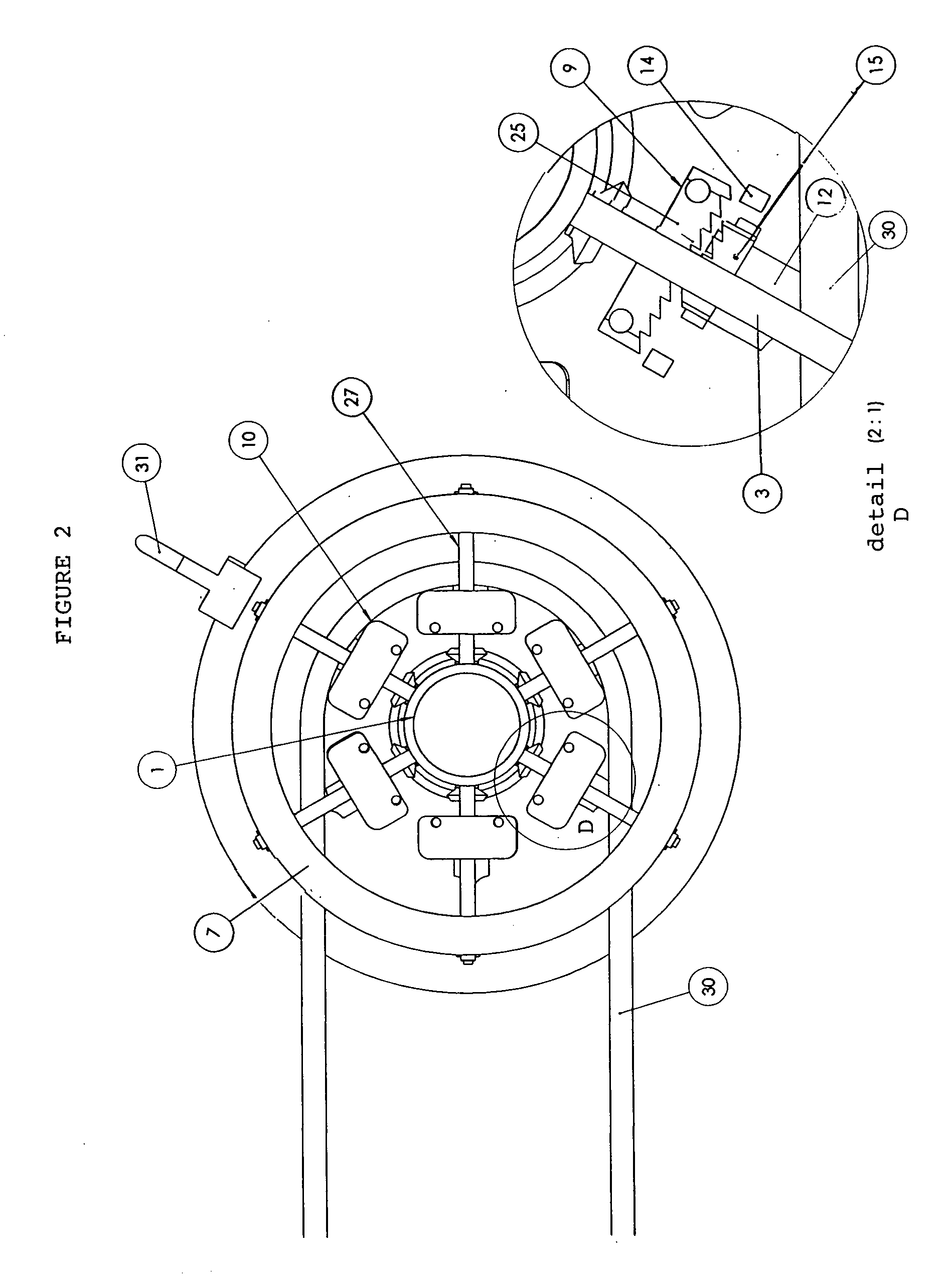
[0112] Each drive in this embodiment includes six platform bodies 10 which form a rotating support. The diameter of the rotating support is continuously variable within a range, as each platform is fitted with a threaded bore (26—better shown in other figures) so that its position may be radially varied by the rotation of a radially oriented worm gear 4. Opposite the worm gear and bore a support rod 3 penetrates a support rod guid...


PUM


Abstract

An improved variable radius chain or belt transmission is provided for bicycle, motorcycle, automobile, industrial, household and consumer product uses. It delivers power and shifts under power through a continuously variable range of ratios. Alternative means are disclosed: for properly engaging the chain or belt regardless of drive radius; for handing off the workload of the chain or belt even while the drive's effective radius is changing; for minimizing the force required to expand a drive under chain or belt; for supporting the chain or belt attachment points in radially variable manner; for circumferentially bridging the spans between radial attachment points; for coordinating the radial movement of the attachment points within one drive; for actuating up-shifting or down-shifting processes in forward or reverse; and for simultaneously varying the effective radii of input and output drives in coordinated fashion.

Description

BACKGROUND OF THE INVENTION [0001] 1. Field of the Invention [0002] The present invention relates generally to transmissions for use in varying input and output torque and speed ratios, such as are commonly used to transmit motor or pedal generated power to one or more rotating output supports such as drive axles in vehicles, including bicycles, automobiles, trucks, tractors, tanks, motorcycles, pedal boats, all-terrain vehicles and snowmobiles and such as turbines, rotors, drills, blades, knives, mills, winches and presses in industrial machines, generators and household appliances, and the like. It relates more particularly to chain and / or belt transmissions in which the effective radius is variable for at least one sprocket wheel, cogwheel or pulley. [0003] 2. Description of Related Art [0004] Transmissions are commonly used to vary transmitted torque and speed in a plurality of ratios between a driver (input) rotating support and a follower (output) rotating support, the two hav...

Claims


Application Information

Patent Timeline
Patent Type & Authority Applications(United States)
IPC IPC(8): F16H55/30F16H55/54
CPCF16H55/54
Inventor GREEN, ARTHUR G.PALLEY, DAVID B.GOLDSBERRY, STEVEN D.
Owner GREEN ARTHUR G
Why Eureka
Try Eureka