Pedicle screw assembly

a technology of pedicle screw and screw body, which is applied in the field of medical devices, can solve the problems of muscle disruption, blood loss, and general invasive nature of standard paraspinal approach used to implant these devices, and achieve the effects of reducing the effect of surgical operation, and reducing the risk of strok

Inactive Publication Date: 2005-10-20
KYPHON
View PDF71 Cites 389 Cited by
  • Summary
  • Abstract
  • Description
  • Claims
  • Application Information

AI Technical Summary

Benefits of technology

[0013] The support structure can be comprised of a material selected from the group consisting of titanium, stainless steel, carbon fiber, a biocompatible material, a reabsorbable material and a composite or combination thereof. Additionally, the support structure can include a central aperture passing from the top surface through to the bottom surface of the support structure. An anchor can be dispos

Problems solved by technology

Some devices for this purpose are designed to be attached directly to the spine, but the generally invasive nature of standard paraspinal approach used to implant thes

Method used


Image

  • Pedicle screw assembly
  • Pedicle screw assembly
  • Pedicle screw assembly

Examples


Embodiment Construction

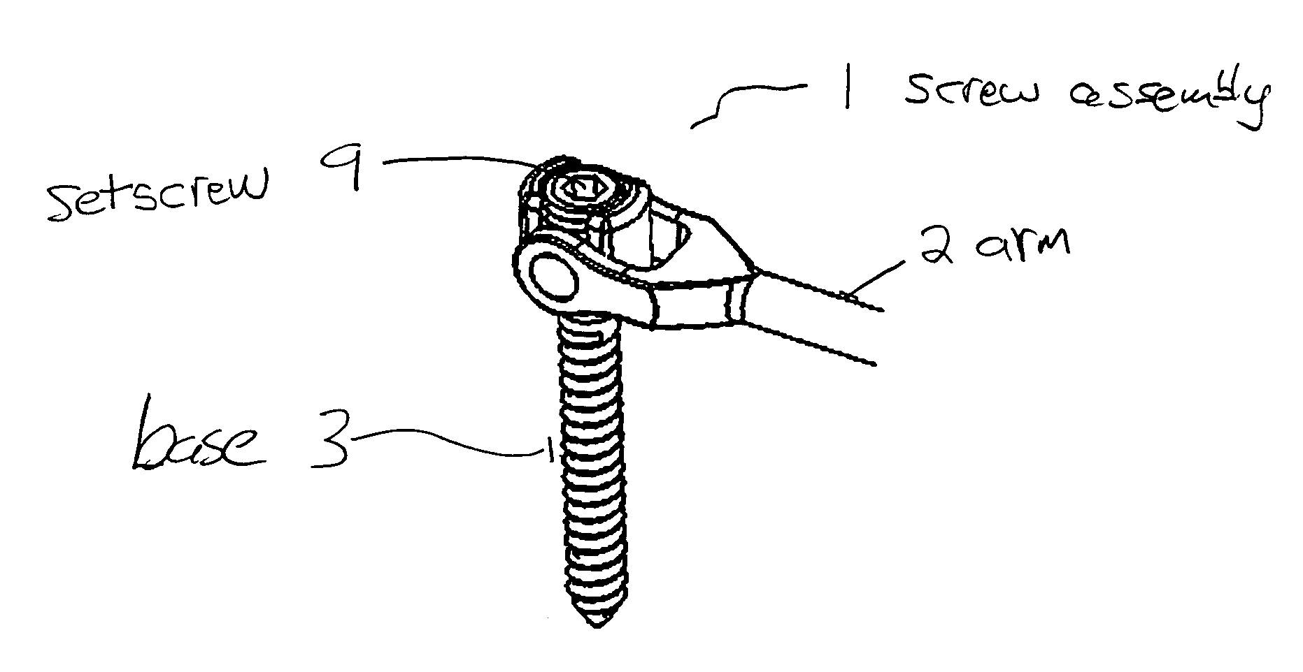
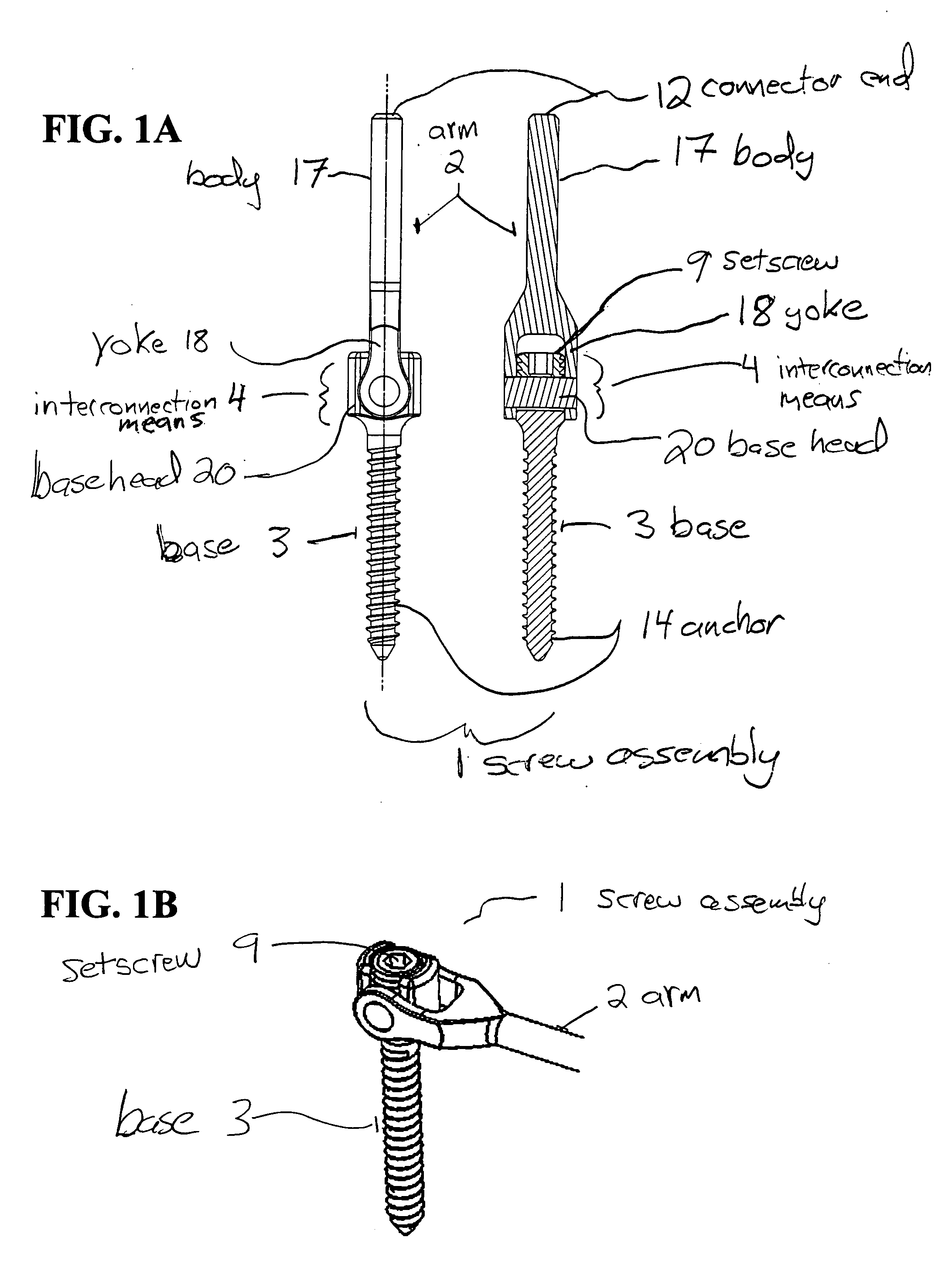
[0036] As shown in FIGS. 1A and 1B, a screw assembly 1 is provided comprised of an arm 2 and a base 3 in a single unit. The screw assembly 1 is elongate and the arm 2 and base 3 of the screw assembly 1, are coupled by an interconnections means 4. Additionally, as shown in FIGS. 1A and 1B, the interconnection means 4 facilitates movement between the arm 2 and the base 3, such that the arm 2 is positionable in a first position that is parallel to a long axis of the base 3 (shown in FIG. 1A) and positionable in a second position that is perpendicular to the long axis of the base 3 (shown in FIG. 1B). The base 3 of the screw assembly 1 is configured for attachment to a structure (e.g., a bone) and the arm 2 is configured for attachment to a support structure 10 (described in detail below). In application, one or more screw assemblies 1 are attached to a support structure 10. Preferably, two screw assemblies 1 are attached to a single support structure 10.

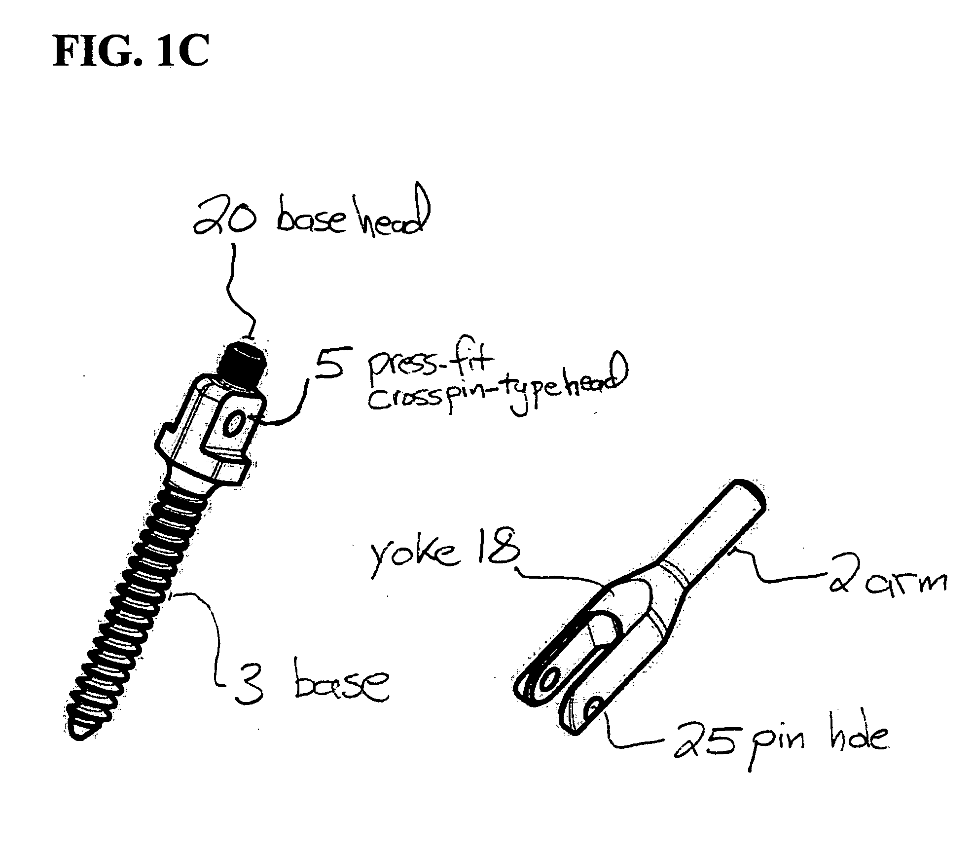
[0037] In an alternative screw ...


PUM


Abstract

A medical device and methods of use thereof are provided for supporting a structure (e.g., bone). A screw assembly is provided that is comprised of a base, an arm, and an interconnection means for coupling the base to the arm. The interconnection means allows the arm to be positionable in a first position that is parallel to a long axis of the base and positionable in a second position that is perpendicular to the long axis of the base. The base is configured for attachment to a structure and the arm configured for attachment to a support structure. A support structure is provided that includes one or more receivers having locking means, which can be configured as an open-ended saddle for attachment to a medical device (e.g., a screw assembly). The support structure is configured to receive one or more medical devices and lock the medical devices to the support structure after installation in a patient.

Description

TECHNICAL FIELD [0001] This invention relates to medical devices. BACKGROUND [0002] The use of bone stabilization / fixation devices to align or position bones is well established. Furthermore, the use of spinal bone stabilization / fixation devices to align or position specific vertebrae or a region of the spine is well established. Typically such devices for the spine utilize a spinal fixation element, comprised of a relatively rigid member such as a plate, board or rod that is used as a coupler between adjacent vertebrae. Such a spinal fixation element can effect a rigid positioning of adjacent vertebrae when attached to the pedicle portion of the vertebrae using pedicle bone anchorage screws. Once the coupled vertebrae are spatially fixed in position, procedures can be performed, healing can proceed or spinal fusion may take place. [0003] Spinal fixation elements may be introduced to stabilize the various vertebrae of the spine. Some devices for this purpose are designed to be attac...

Claims


Application Information

Patent Timeline
IPC IPC(8): A61B17/58A61B17/70A61B17/88
CPCA61B17/7005A61B17/7007A61B17/7085A61B17/705A61B17/7082A61B17/7032
Inventor MARKWORTH, AARON D.
Owner KYPHON
Why Eureka
Try Eureka