
Synchronous formal language for programming deterministic finite state machines

a deterministic finite state machine and synchronous formal language technology, applied in the field of computer programs and systems, can solve the problems of difficult to program deterministic finite state machines, graphical interfaces unfamiliar to automation specialists, and program execution of programs written in one of these languages

Inactive Publication Date: 2005-10-20
ATHYS
View PDF2 Cites 6 Cited by
  • Summary
  • Abstract
  • Description
  • Claims
  • Application Information

AI Technical Summary

Benefits of technology

"The invention provides a language for programming deterministic finite state machines controlling a physical process. This language includes a graphical representation of the behavior of a finite state machine, with values for various flags and transitions between steps. The language also includes a process for programming the machine using this language, as well as a computer system for implementing the language. The technical effect of this invention is to provide a more intuitive and efficient way to program these machines, allowing for easier understanding and debugging of the code."

Problems solved by technology

However, these languages are not formal languages; one of the main drawbacks is therefore that the execution of a program written in one of these languages may differ from a machine to the other.
SFC, as a language, is no formal, in that it is not possible to unambiguously define whether a SFC graph is well-formed and will therefore have a certain effect when applied to a given finite state machine.
It is provided with a graphical interface, called SyncChart; however, this graphical interface is not familiar to automation specialists, which is a bar to the extensive use of ESTEREL STUDIO in the field of automation.
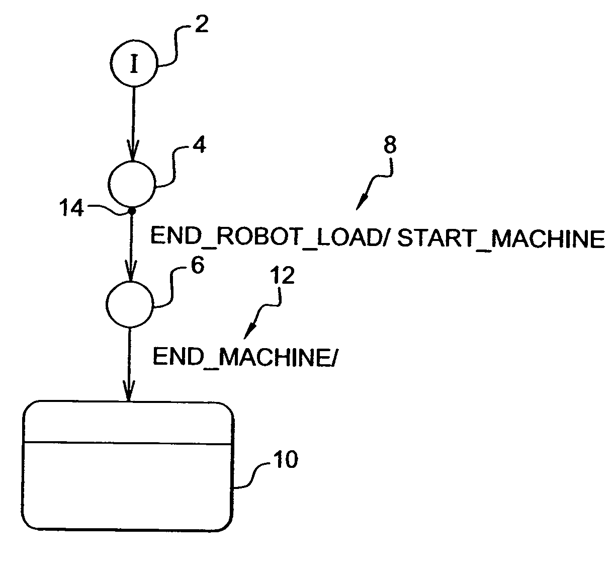
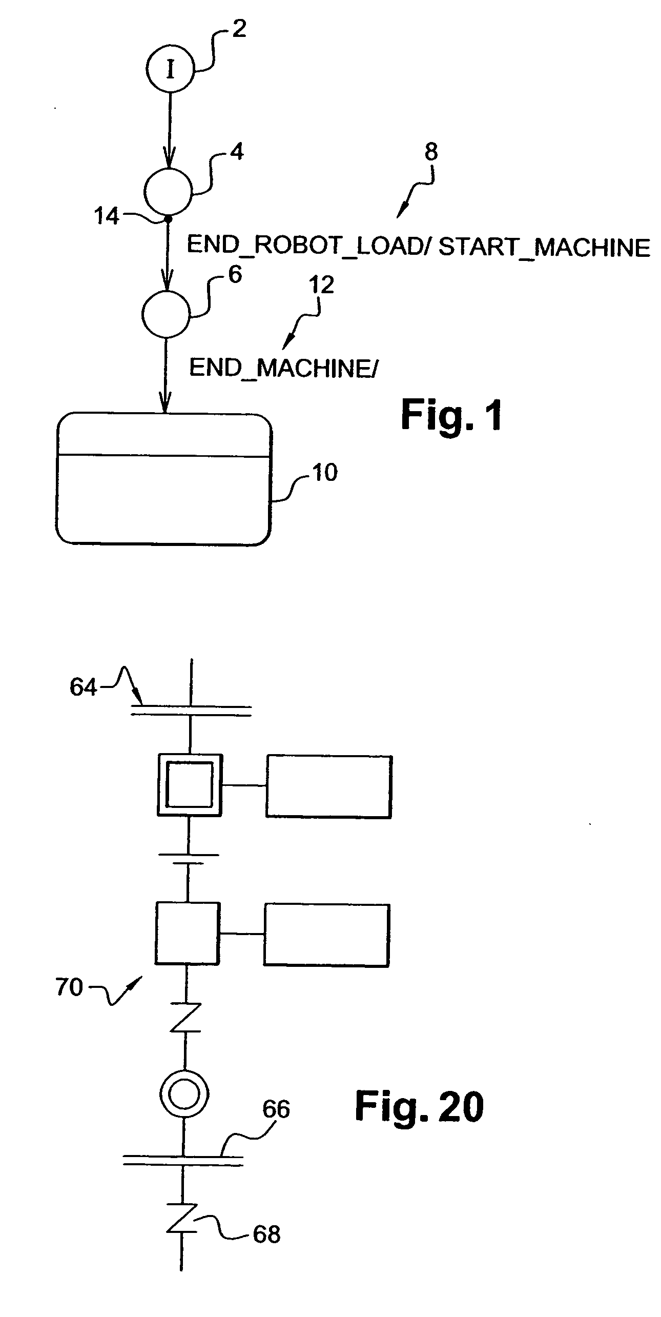
The graphical interface of ESTEREL STUDIO, as exemplified in FIG. 1, makes it difficult to program deterministic finite state machines.

Method used


Image

  • Synchronous formal language for programming deterministic finite state machines
  • Synchronous formal language for programming deterministic finite state machines
  • Synchronous formal language for programming deterministic finite state machines

Examples


Embodiment Construction

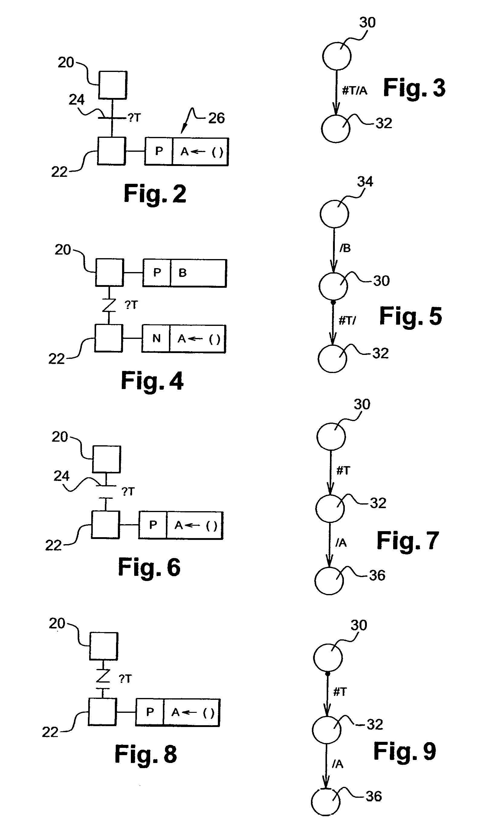
[0049] The invention provides a synchronous formal language for programming deterministic finite state machines. The language includes a graphical representation, where the behaviour of a finite state machine is represented as a graph of steps and transitions. Actions are associated with steps. A transition between two steps includes: [0050] at least a pause flag, controlling the cycle during which the transition is evaluated; and [0051] a pre-emption flag, according to which the transition is evaluated before or after an action associated with the transition is executed.

[0052] The flag are graphically represented, and not textually represented. This makes it possible to graphically represent in a compact and easy way the various possible transitions of a deterministic finite state machine between its various steps. In addition, this makes it possible for a compiler to analyse the transitions and their attributes, without having to consider the textual information regarding the con...


PUM


Abstract

A synchronous formal language is used for programming deterministic finite state machines. The language includes a graphical interface, where the behaviour of a finite state machine is represented as a graph of steps and transitions. Actions are actions are associated with steps. A transition between two steps includes: a pause flag, controlling the cycle during which a condition associated with the transition is evaluated; and a pre-emption flag, according to which the condition associated with the transition is evaluated before or after an action associated with the step preceding the transition is executed. The invention makes it possible for the user to have a graphical representation of the attributes of all types of transitions, without the need to use any text. The representation is simple and compact.

Description

CROSS REFERENCE TO RELATED APPLICATIONS [0001] This application claims priority to European patent application no. 04291023.2 filed Apr. 16, 2004. FIELD OF THE INVENTION [0002] The invention relates to the field of computers programs and systems, and more specifically to programming of real time systems. BACKGROUND OF THE INVENTION [0003] Finite State Machines is required for the programming of a lot of Real time system programming. Examples of such deterministic final state machines include programmable logic controllers (PLC's), which are used for automating industrial systems. More generally, Final State Machines are machines that react to inputs given by an external environment. The behavior of such reactive machines is cyclic and each cycle can be generally decomposed in 4 steps: [0004] inactive or waiting time; [0005] reading inputs; [0006] active or computing; [0007] writing outputs. [0008] In those systems, usually inputs are not read during computation. The system can there...

Claims


Application Information

Patent Timeline
Patent Type & Authority Applications(United States)
IPC IPC(8): G05B19/045G06F9/45G05B19/05G06F9/44
CPCG05B2219/23286G05B19/045G08G1/0968G07C5/00
Inventor AUDFRAY, PHILIPPECLOSSE, ETIENNEWEIL, DANIELCOMBET-BLANC, FRANK
Owner ATHYS
Learn More