Robotic vacuum cleaner

a robotic vacuum cleaner and vacuum cleaner technology, applied in the direction of vehicle position/course/altitude control, process and machine control, instruments, etc., can solve the problems of large distance, damage to the robotic vacuum cleaner, and inability to easily reach the edges of obstacles, etc., to achieve a better cleaning

Active Publication Date: 2005-10-27
HUNAN GRAND PRO ROBOT TECH
View PDF5 Cites 133 Cited by
  • Summary
  • Abstract
  • Description
  • Claims
  • Application Information

AI Technical Summary

Benefits of technology

[0008] The object of the present invention is to provide a robotic vacuum cle...

Problems solved by technology

Although the robotic vacuum cleaner 100 is moved substantially over the entire floor surface to be cleaned, it cannot easily reach edges of the obstacle 91 like corners of the wall or edges of furniture.
While higher sensitivity can achieve a better cleaning effect, it may increase cha...

Method used


Image

  • Robotic vacuum cleaner
  • Robotic vacuum cleaner
  • Robotic vacuum cleaner

Examples


Embodiment Construction

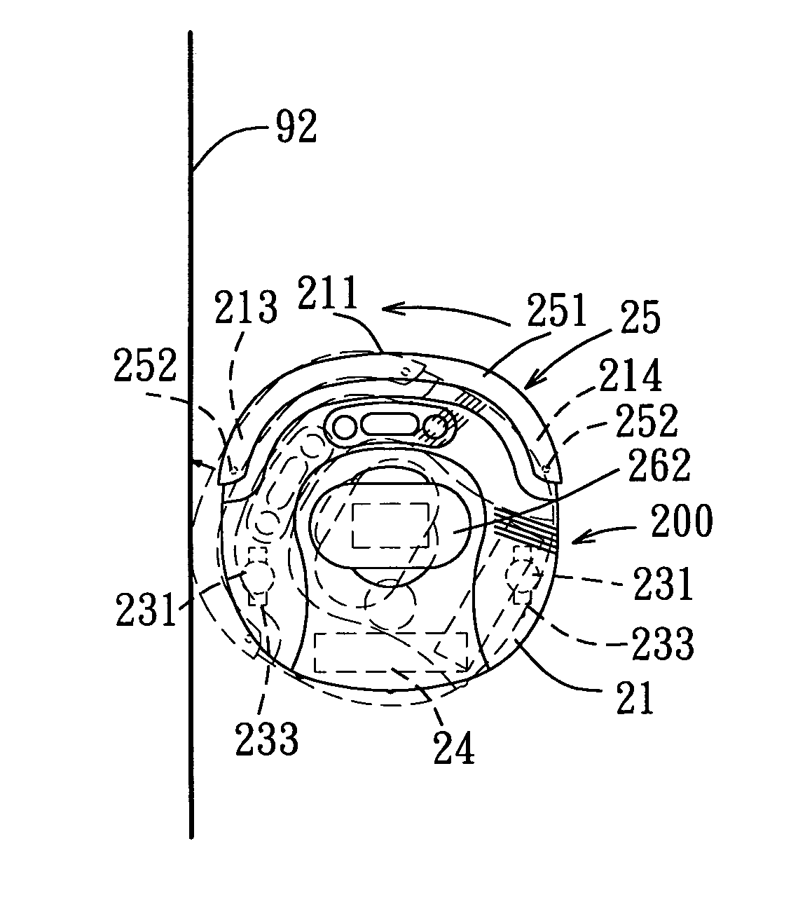
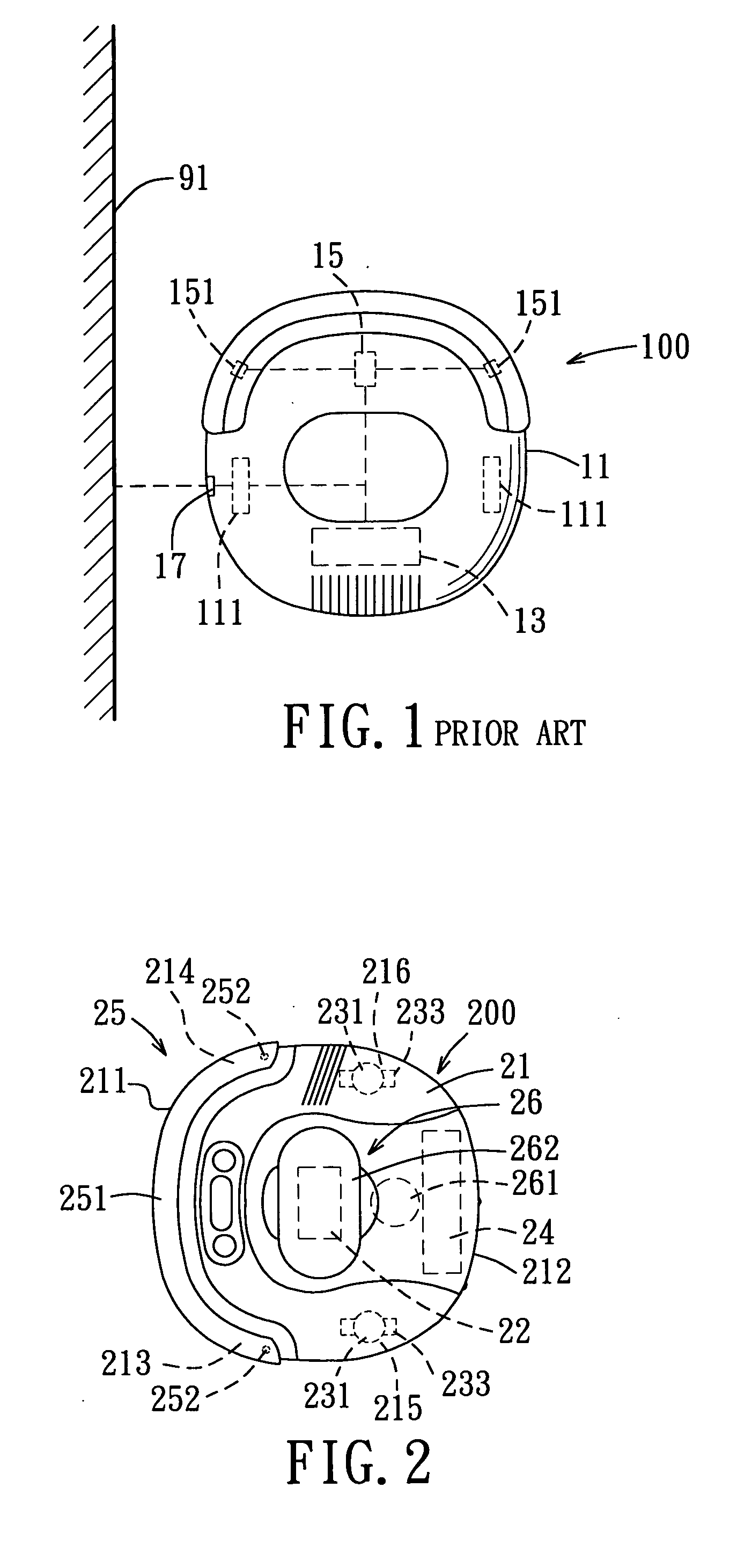
[0017] Referring to FIG. 2, the preferred embodiment of a robotic vacuum cleaner 200 according to the present invention is shown to comprise a casing 21, a suction unit 26, a motor-driven wheel unit, a drive motor unit, a tactile sensor unit 25, and an electrical control unit 22.

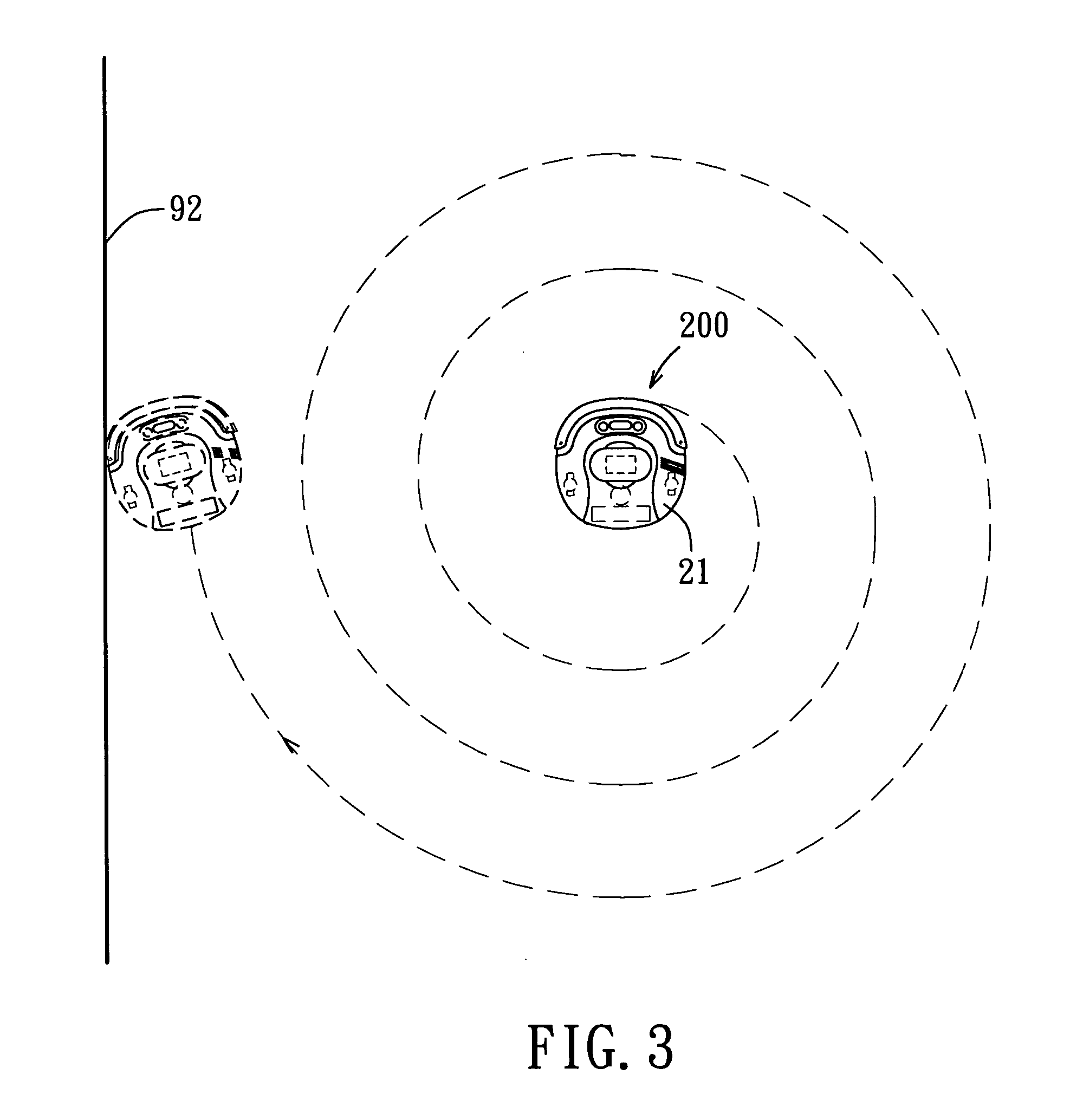
[0018] The casing 21 has a lower major wall 212 which is adapted to confront a floor surface to be cleaned, and which includes a central area that defines a central axis normal to the central major wall, and a surrounding peripheral area that surrounds the central area about the central axis. The surrounding peripheral area includes a leading region 211 which is positioned ahead of the central area when the casing 21 is driven to move along the floor surface, left and right front regions 213, 214 which flank the leading region 211, and left and right rear regions 215, 216 which are disposed rearwardly of the left and right front regions 213, 214, respectively.

[0019] The suction unit 26 is disposed in the l...


PUM


Abstract

A robotic vacuum cleaner includes a casing with a motor-driven wheel unit mounted on a lower major wall thereof, and a tactile sensor unit yieldable radially relative to the casing. An electrical control unit is operable to control the wheel unit to operate in a starting mode in which the casing is moved along a spiral path, and, upon receipt of a switching signal generated by the sensor unit in response to a contact of the sensor unit with an obstacle, controls the wheel unit to operate in an edge-cleaning mode in which the wheel unit is initially turned to a normal angle, is then driven to move forward a predetermined distance, is subsequently turned to an activating angle, and is moved towards the obstacle to permit contact of the sensor unit with the obstacle so as to result in generation of switch signal enabling the wheel unit to continue to operate in the edge-cleaning mode.

Description

CROSS-REFERENCE TO RELATED APPLICATION [0001] This application claims priorities of Taiwanese Application No. 093111106, filed on Apr. 21, 2004, and Taiwanese Application No. 093117349, filed on Jun. 16, 2004. BACKGROUND OF THE INVENTION [0002] 1. Field of the Invention [0003] This invention relates to a robotic vacuum cleaner, more particularly to a robotic vacuum cleaner which can proceed with an edge-cleaning mode for improving the cleaning effect. [0004] 2. Description of the Related Art [0005] Referring to FIG. 1, a conventional robotic vacuum cleaner 100 is shown to include a casing 11, a plurality of motor-driven wheels 111, a plurality of drive motors (not shown) disposed to drive the wheels 111 so as to move the casing 11 along a floor surface to be cleaned, an electrical control unit 13, and a sensing unit 15. A variety of path programs are stored in the electrical control unit 13 to control the drive motors so as to selectively steer the wheels 111 to cause backward or fo...

Claims


Application Information

Patent Timeline
IPC IPC(8): A47L5/00A47L9/00G05D1/02
CPCA47L9/009A47L2201/04G05D2201/0215G05D1/0227
Inventor YAN, JASON
Owner HUNAN GRAND PRO ROBOT TECH
Why Eureka
Try Eureka