

Linear into rotatory or vice versa motion convertor
a technology of linear motion and convertor, which is applied in the direction of connecting rods, steering rudders, bearings, etc., can solve the problems of high stress, wear and/or breakage, and limited arrangement, so as to shorten the duration of the power stroke, and increase the mean velocity of the piston over the power stroke
- Summary
- Abstract
- Description
- Claims
- Application Information
AI Technical Summary
Benefits of technology
Problems solved by technology
Method used
Image

Examples
Embodiment Construction
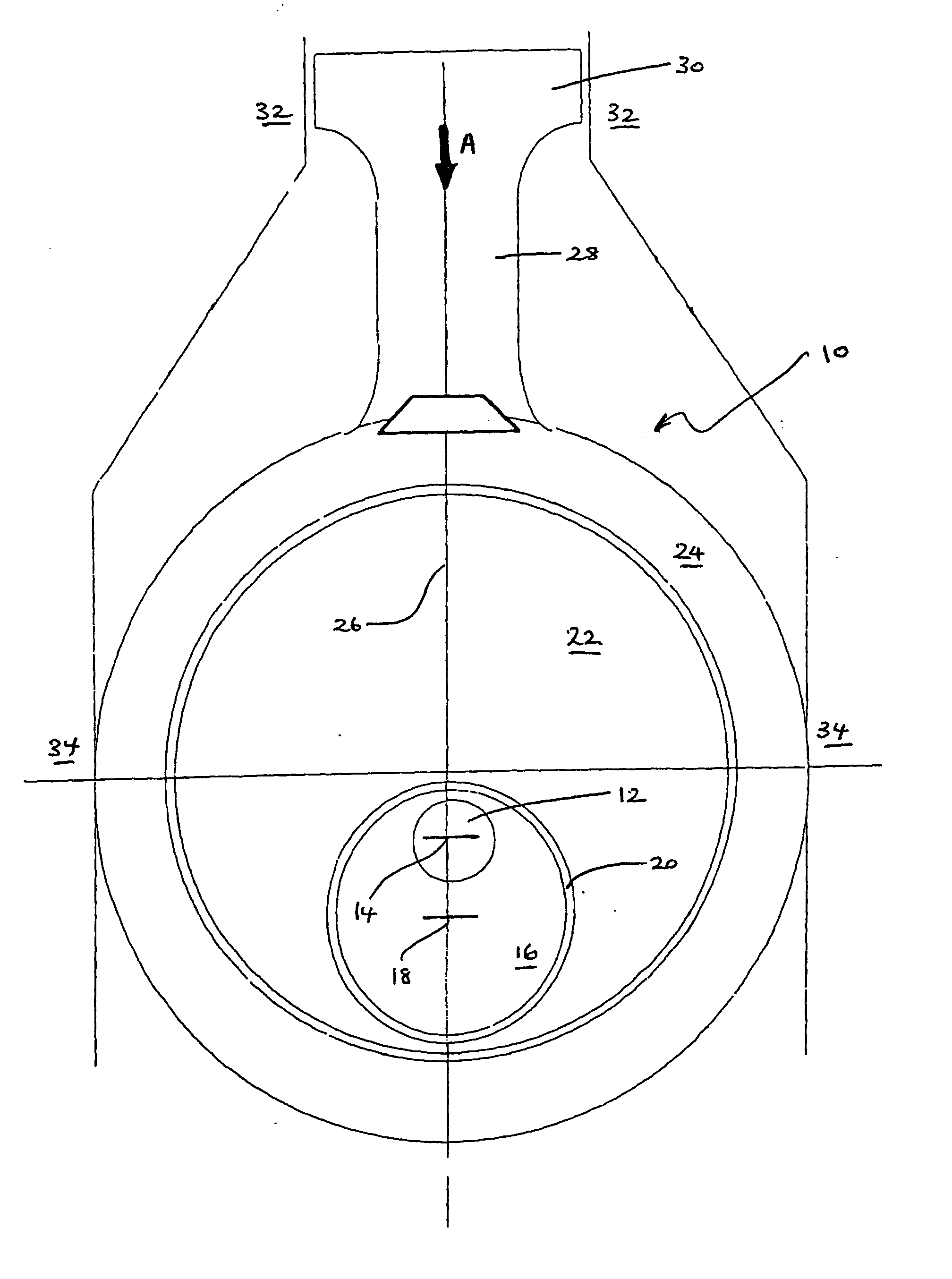
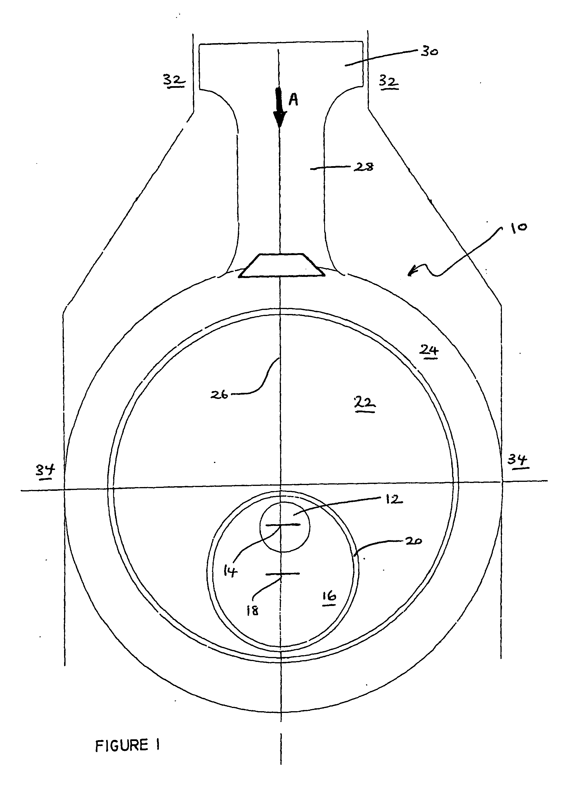
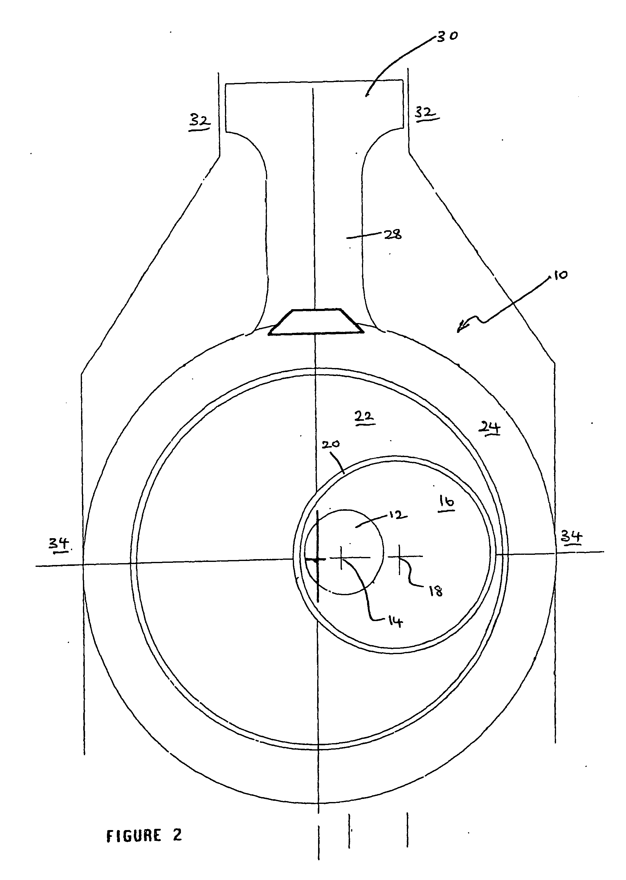
[0023] Referring firstly to FIG. 1, an apparatus 10 for converting linear motion into rotary motion is shown as including a shaft 12 which is rotatable about a fixed axis 14 and carries a circular cam 16. The circular cam 16 is mounted eccentrically relative to the shaft 12 such that a central axis 18 of the cam 16 is spaced from the fixed axis 14. The cam 16 is rotatably mounted within a correspondingly dimensioned circular cavity 20 formed in a journal (in the form of disc 22) which is co-planar with the cam 16. The disc 22 is rotatably mounted within a housing 24 mounted for reciprocating motion along a second, rectilinear axis 26 in a direction transverse to the fixed axis 14 of the shaft 12. The reciprocating motion of the housing 24 along the rectilinear axis 26 is converted into rotation of the shaft 12. A connecting rod 28 is integrally formed with the housing 24, and is integrally formed at its other end to a piston 30.
[0024] The apparatus 10 may be used in an internal com...
PUM
 Abstract
Description
Claims
Application Information