Acoustic flow pulsing apparatus and method for drill string

a technology of pulsing apparatus and drill string, which is applied in the direction of survey, directional drilling, borehole/well accessories, etc., can solve the problems of wasting energy, increasing the penetration rate, and extremely expensive operation of drilling a deep underground well

Inactive Publication Date: 2005-10-27
LEWAL DRILLING
View PDF19 Cites 22 Cited by
  • Summary
  • Abstract
  • Description
  • Claims
  • Application Information

AI Technical Summary

Problems solved by technology

Drilling a deep underground well is an extremely expensive operation.
However, if inadequate cleaning takes place, further increases in the drill bit weight do not cause corresponding increases in penetration rate because rock chips not cleared away are being reground, thus wasting energy.
Mud hammers are expensive to operate as drill bit life is significantly reduced by the use of a mud hammer.
While the devices described in these patents have proven to be effective at increasing drilling penetration rates they have a number of disadvantages which has prevented their widespread adoption.
It is difficult to design such a tool which will operate reliably under the constantly changing properties of drilling mud and the constantly increasing hydrostatic pressure at downhole locations.
This problem is exacerbated by the small space within which downhole tools must fit.
Space constraints impose onerous constraints on the design of such tools.
Other problems with these devices include: Downhole conditions are harsh.
Operating parts of these tools may not withstand downhole operating conditions for extended periods of time.
Operating parameters cannot be adjusted while drilling is ongoing.
This makes it difficult to optimize the performance of these tools.
It is not possible to switch these tools on or off while drilling.
This makes it difficult to ascertain the effectiveness of the tools since there is a significant variation in drilling penetration rates from well-to-well even if all drilling parameters are kept constant.
During drilling, these tools are only accessible for repair when they are brought to the surface.

Method used


Image

  • Acoustic flow pulsing apparatus and method for drill string
  • Acoustic flow pulsing apparatus and method for drill string
  • Acoustic flow pulsing apparatus and method for drill string

Examples


Embodiment Construction

[0041] As required, detailed embodiments of the present invention are disclosed herein. However, it is to be understood that the disclosed embodiments are merely exemplary of the invention, which may be embodied in various forms. Therefore, specific structural and functional details disclosed herein are not to be determined as limiting, but merely as a basis for the claims and a representative basis for teaching one skilled in the art to variously employ the present invention in virtually any appropriately detailed structure.

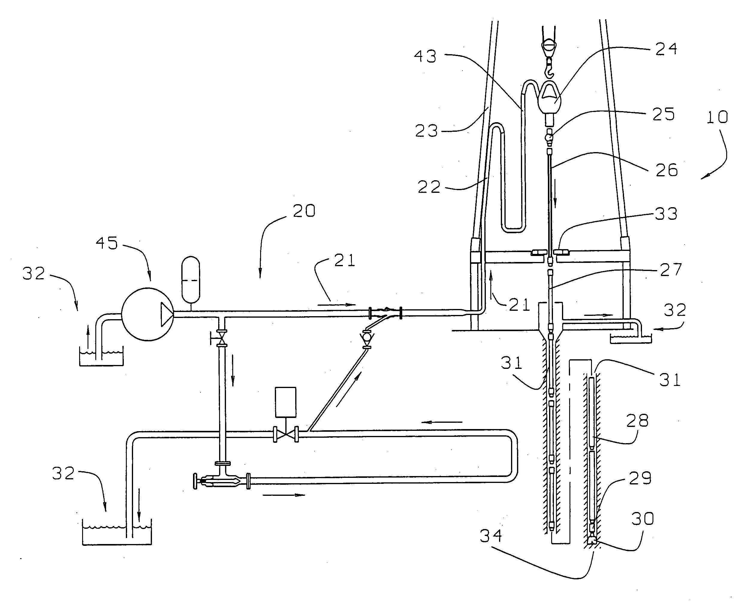
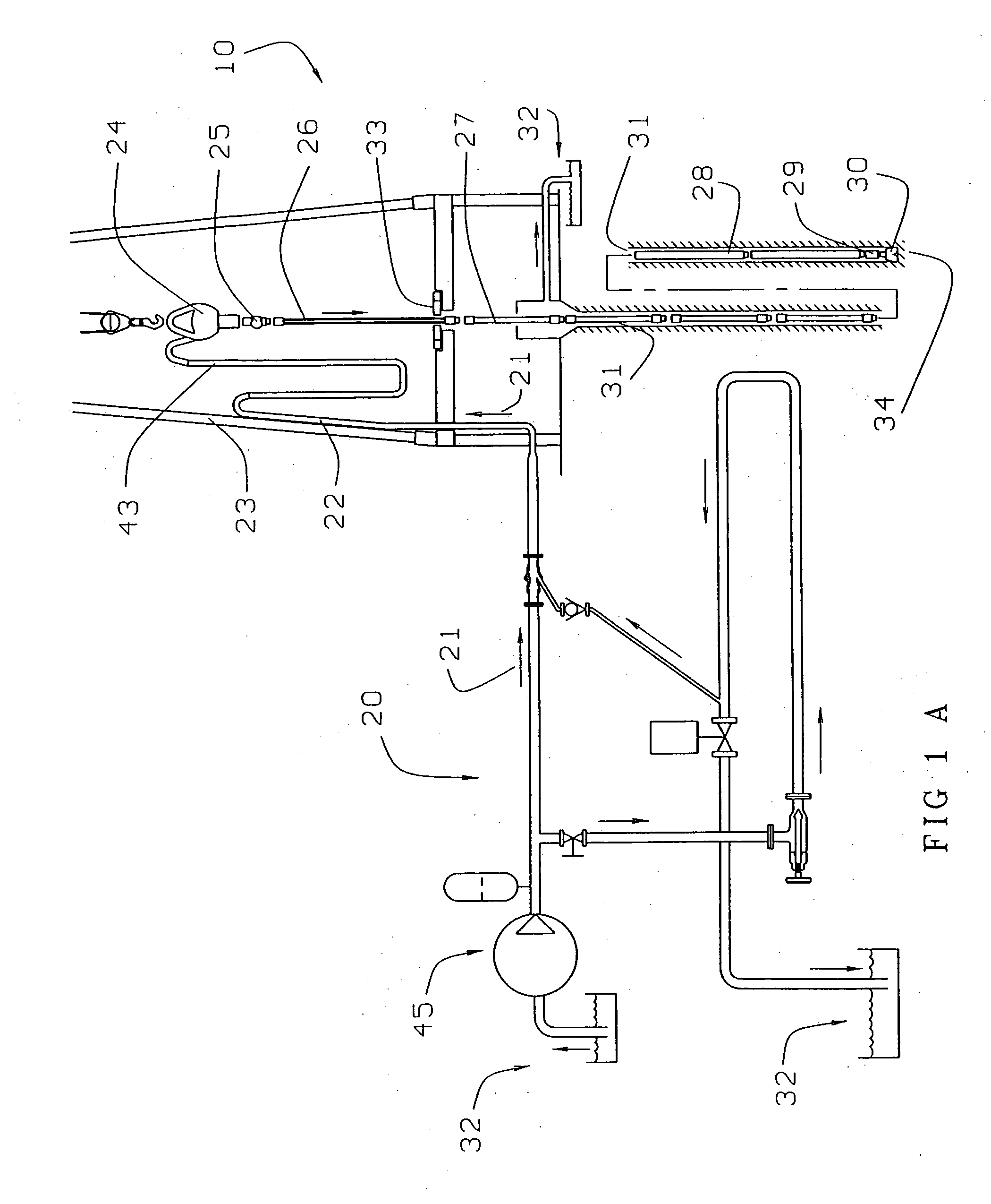
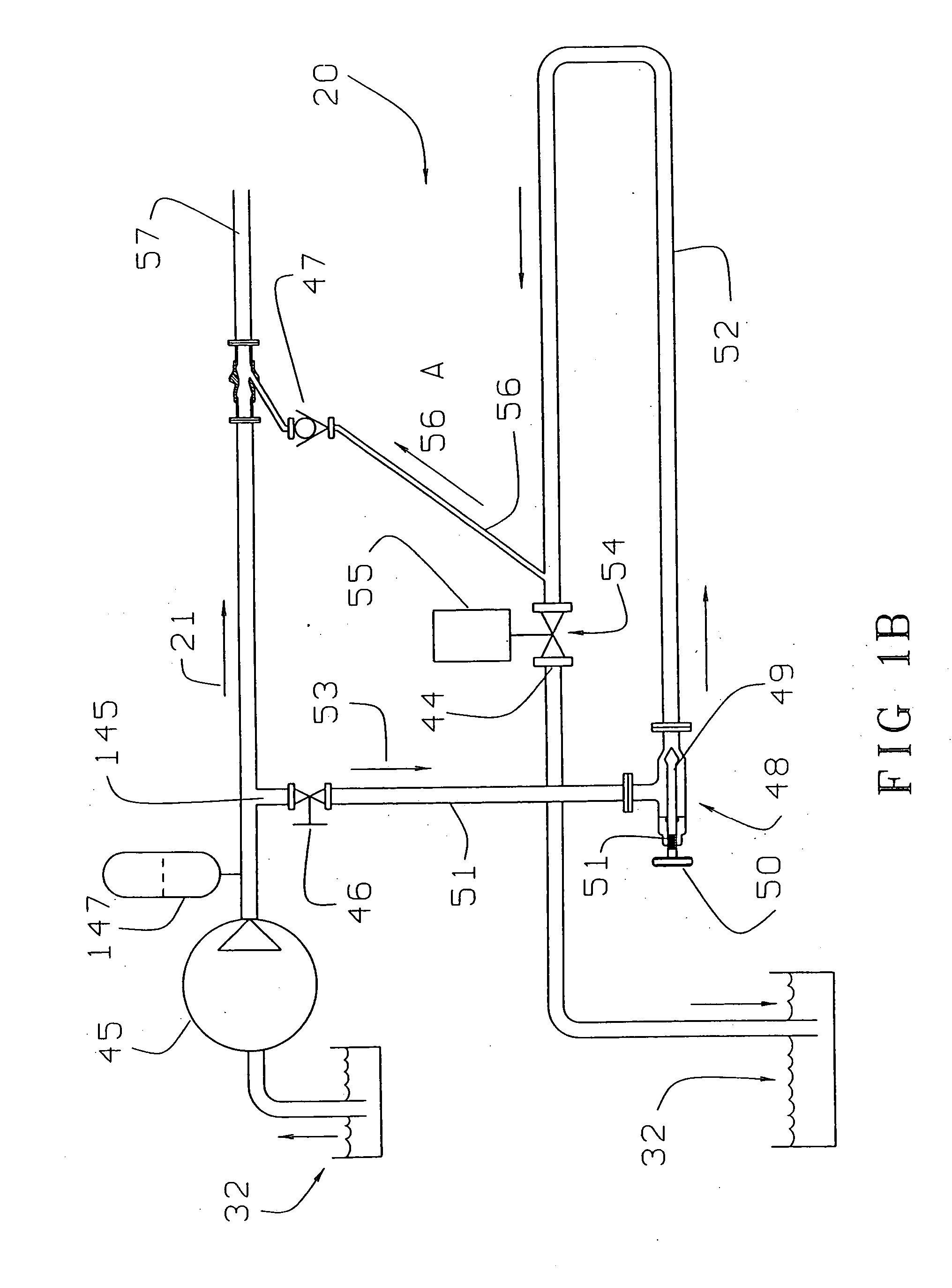
[0042] This invention provides methods for generating acoustic pulses at the surface and conveying such pulses downhole to downhole tools and / or a drill bit. In preferred embodiments of the invention, acoustic pulses are generated by interrupting the flow of drilling mud in a conduit and thereby causing water hammer in the conduit.

[0043]FIG. 1A is a schematic view of a typical rotary drilling apparatus 10 which has been modified by the addition of a surface ac...


PUM


Abstract

An underground drilling method and apparatus generates intense pressure pulses at a location at the surface. The pressure pulses propagate down through a drill string to a drill bit. The pulses may be generated by creating water hammer in flowing drilling mud. Intensity of the acoustic pulses is increased in the bit nozzles. Vigorous pulsing of the fluid exiting the bit nozzles results in better cleaning of the hole bottom and faster drilling. The pulses may be used to drive the operation of various down hole tools. One type of tool has multiple pistons arranged in series. High pressure pulses move the pistons to generate strong mechanical vibration in the drill string. Vibration of the drill string may also reduce the friction between the drill string and the hole, resulting in lower torque requirements.

Description

CROSS-REFERENCE TO RELATED APPLICATIONS [0001] This is a continuation of U.S. patent application Ser. No. 10 / 614,258 filed 8 Jul. 2003 entitled ACOUSTIC FLOW PULSING APPARATUS AND METHOD FOR DRILL STRING, which is a continuation of PCT / CA02 / 00020 filed 9 Jan. 2002 entitled PRESSURE PULSING APPARATUS AT SURFACE AND METHOD FOR DRILLING, which designates the United States of America and which is hereby incorporated herein by reference. This application is related to and claims the benefit of the filing dates of Canadian patent application No. 2,331,021 filed on 9 Jan., 2001 and Canadian patent application No. 2,354,994 filed on 13 Aug. 2001.FIELD OF THE INVENTION [0002] This invention relates to underground drilling. In particular, the invention relates to underground drilling methods which involve the creation of acoustic pulses in drilling fluid, the use of such pulses to operate downhole tools, and the use of such pulses to increase drilling rates. The invention also relates to appa...

Claims


Application Information

Patent Timeline
Patent Type & Authority Applications(United States)
IPC IPC(8): E21B4/20E21B7/24E21B21/10
CPCE21B4/20E21B21/106E21B7/24
Inventor WALTER, BRUNO
Owner LEWAL DRILLING
Why Eureka
Try Eureka