Curved electrode for welding

a technology of curved electrodes and electrode holders, which is applied in the direction of resistance electrode holders, welding apparatus, manufacturing tools, etc., can solve the problems of difficulty in inserting water supply tubes in cases, and achieve the effects of reducing work volume, reducing cost, and sufficient structural strength

Inactive Publication Date: 2005-10-27
SMK CO LTD
View PDF6 Cites 14 Cited by
  • Summary
  • Abstract
  • Description
  • Claims
  • Application Information

AI Technical Summary

Benefits of technology

[0021] The seal ring prevents water from leaking from the engagement portion. A single seal ring may be provided on the upper side. Two seal rings may be provided such that the intersecting portion of the holes is located therebetween. A groove for the seal ring may be formed in either of the installing portion or the offset portion. However, when the groove for the seal ring is formed in the installing portion, the work amount can be reduced so as to reduce the cost. The line diameter of the seal ring needs to be 0.1 mmφ or more, and preferably around 1 / 50-⅕ mmφ with respect to the outer diameter of the installing portion. If the line diameter is less than 0.1 mmφ, hardly any sealing effect is achieved. If the line diameter is more than ⅕ mmφ with respect to the outer diameter of the installing portion, there are cases where sufficient structural strength cannot be achieved.
[0022] Also, as a result of a durability test, it turned out that the durability is 20-30 times higher in the case of forming the groove for the seal ring in the installing portion than the case of forming the groove in the offset portion. The reasons are as follows. In the case of forming the groove for the seal ring in the offset portion as a female taper, since stress is applied in a direction where the inner diameter taper portion expands at the time of welding and warpage easily occurs, the cooling water tends to leak and the durability of the electrode is deteriorated. In contrast, in the case of forming the groove for the seal ring in the installing portion as a male taper, since stress is applied in a direction where the outer diameter taper portion shrinks at the time of welding, and also the strength of the rod body is large, the cooling water hardly leaks. In addition, when a curved electrode is used in an actual welding operation field, it is common for an operator to install or remove the curved electrode by hitting the curved electrode with a hammer. In particular, in order to easily install or remove the curved portion, a process of hitting the upper portion, the left and the right of the engagement portion is employed. In this process, the sealing effect is more easily deteriorated in the case of providing the seal ring in the offset portion than the case of providing the seal ring in the installing portion. A test result shows that the durability is 50-60 times higher in the case of providing the seal ring in the installing portion than the case of providing the seal ring in the offset portion.
[0023] As mentioned above, according to the present invention, by forming at least the installing portion separately from the offset portion and the tip portion, the curved electrode can be manufactured easily at a low cost. If a part of it is damaged, only that part needs to be replaced at a low cost.
[0024] Also, the water supply tube can be inserted securely by conducting C-chamfering or R-chamfering to the corner of the two holes of the substantially T-shaped or L-shaped hole. In addition, since the press-fitting amount between the installing portion and the offset portion is set in a predetermined range, the installing portion and the offset portion can be coupled securely so as to prevent water or the like from leaking.
[0025] In addition, the R-chamfered portions provided on the periphery of the opening on the press-fitting side of the tapered hole and the periphery of the end of the tapered portion makes the press-fitting smooth, and the seal ring interposed in the engagement interface between the tapered hole and the tapered portion can securely prevent water from leaking.

Problems solved by technology

In contrast, it is difficult to insert a water supply tube in a case where two holes are only intersected because a burr sticks out in a corner of the intersecting portion where the tube passes or the shape of the corner is sharp.

Method used


Image

  • Curved electrode for welding
  • Curved electrode for welding
  • Curved electrode for welding

Examples


Embodiment Construction

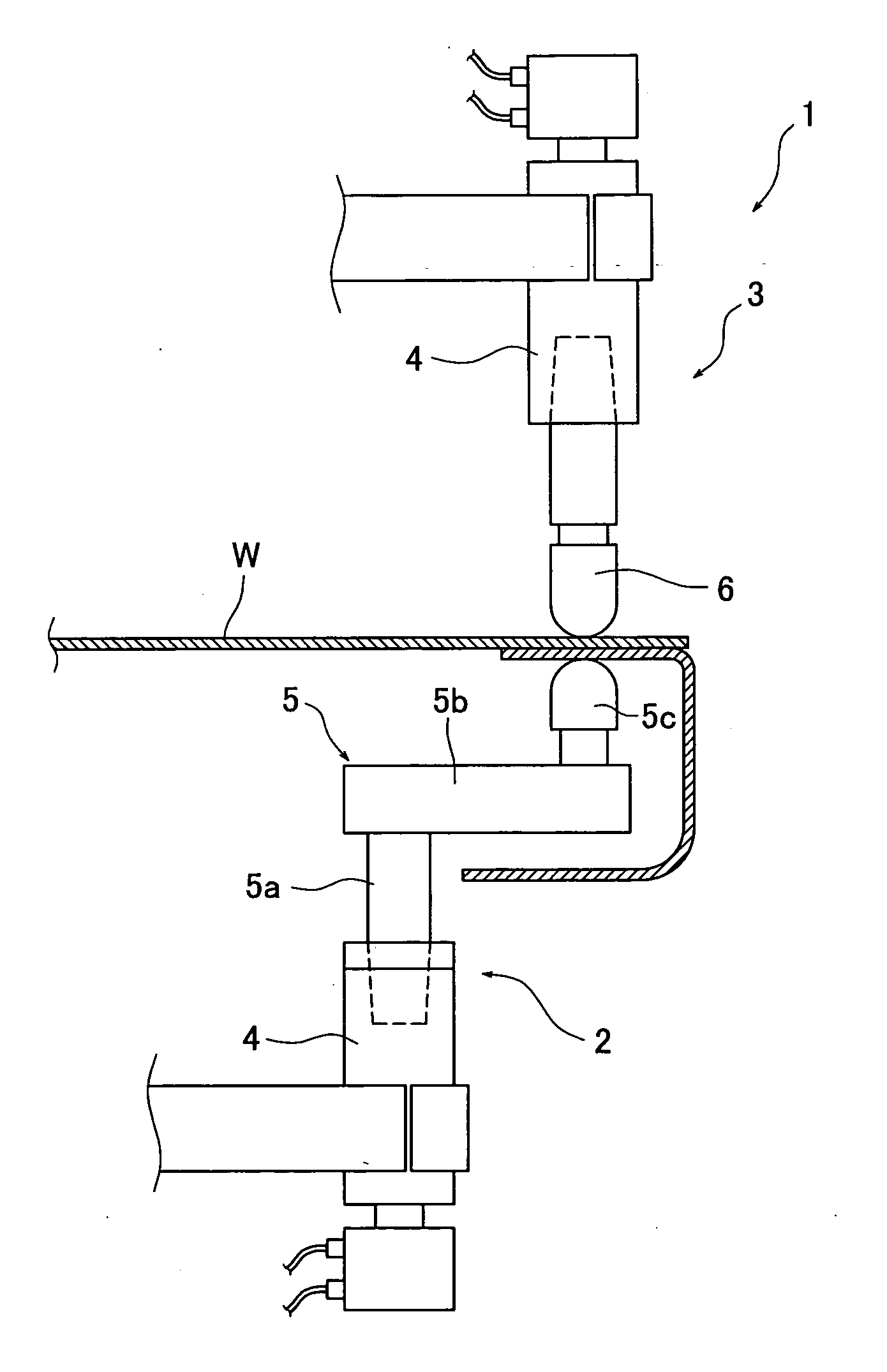
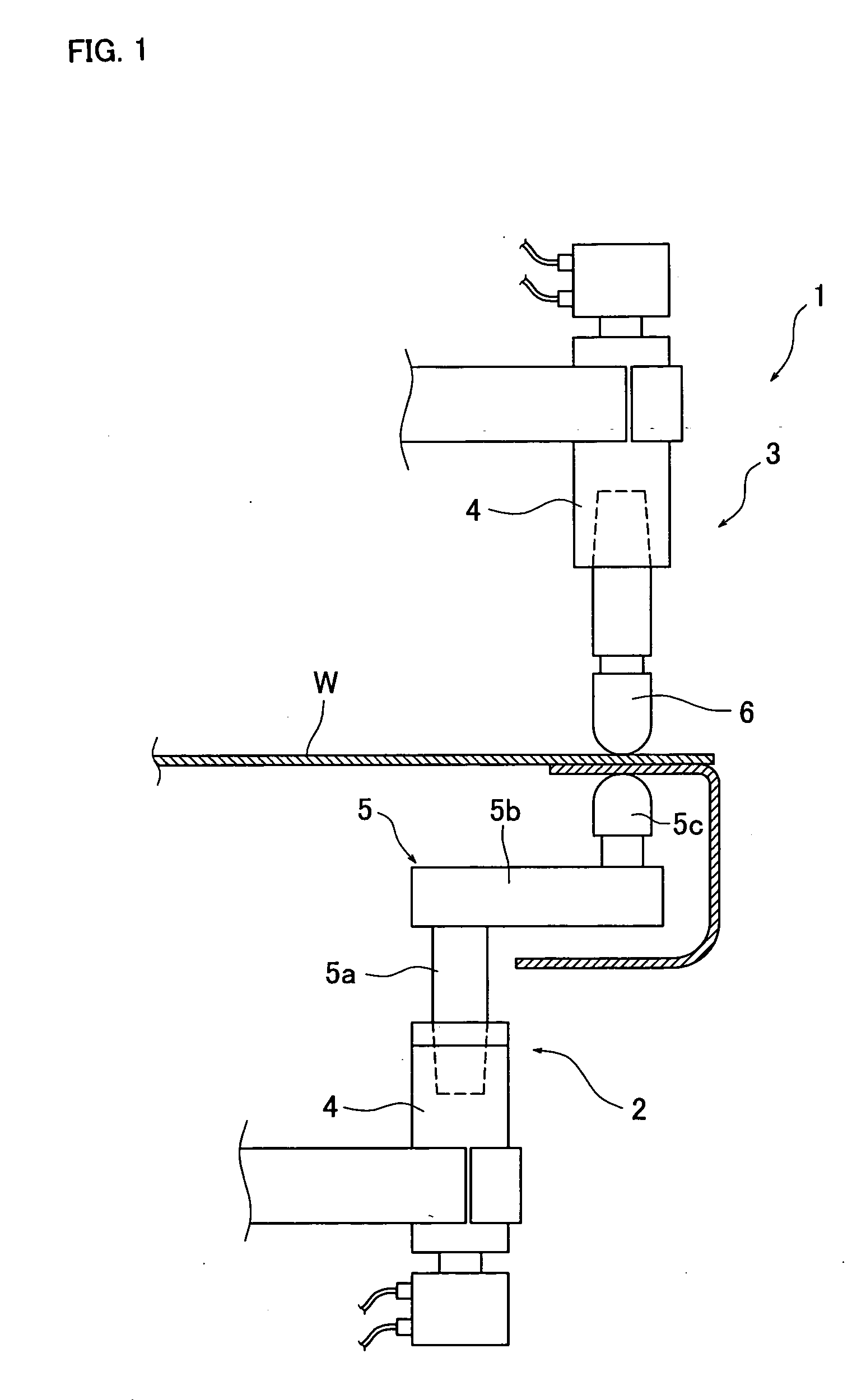
[0032] Preferred embodiments of the present invention will now be described with reference to the accompanying drawings. FIG. 1 is a view explaining an example of a welding apparatus in which a curved electrode according to the present invention is used, FIG. 2 is an exploded view of the curved electrode, FIG. 3 is a sectional view of the curved electrode, FIG. 4 is a view explaining a test result in which the press-fitting amount of the installing portion is changed, and FIG. 5 is a view explaining a state of chamfering a first tapered hole of the offset portion and a tapered portion of the installing portion.

[0033] The curved electrode according to the present invention can be manufactured easily at a low cost even in a case where the offset amount is different. Also, even if a part of it is damaged, only the damaged part needs to be replaced. In addition, the durability can be improved at the same time by directly cooling the inside. The curved electrode according to the present...


PUM

PropertyMeasurementUnit
radiusaaaaaaaaaa
outer diameteraaaaaaaaaa
diameteraaaaaaaaaa

Abstract

A curved electrode includes an installing portion to be installed in an electrode holder, an offset portion by which the offset amount is obtained, and a tip portion which comes into contact with the material to be welded W, the portions being formed separately and assembled together. A vertical hole and a horizontal hole are formed within the installing portion, an axis hole is formed within the offset portion, and a water supply tube is inserted into a cooling hole which is constructed of the vertical hole, the horizontal hole and the axis hole. C-chamfering or R-chamfering is conducted to a corner where the vertical hole and the horizontal hole intersect. An object of the present invention is to provide a curved electrode which can be manufactured easily at a low cost, and if a part of it is damaged, only that part needs to be replaced at a low cost. The durability of the curved electrode can be improved at the same time.

Description

BACKGROUND OF THE INVENTION [0001] 1. Field of the Invention [0002] The present invention relates to an improved curved electrode which is used for a resistance welding apparatus, for example. [0003] 2. Description of the Prior Art [0004] Conventionally, in an apparatus for resistance welding such as spot welding or the like, an electrode having a curved shape is used due to the shape of a material to be welded. As for the electrode having a curved shape, if the offset amount is too large, excessive moment is applied to the installing portion of the electrode due to an applied load at the time of welding. In this case, if the installing portion is fixed by taper engagement, the tapered hole is deformed into an elliptical shape, thus, it cannot be used. Therefore, there has been known a technique in which the vicinity of the installing portion of the electrode is retained by a cap nut (See Document 1). [0005] [Document 1] Japanese Patent Application Publication No. 7-60458 [0006] In ...

Claims


Application Information

Patent Timeline
Patent Type & Authority Applications(United States)
IPC IPC(8): B23K11/30B23K11/31B23K35/02
CPCB23K35/0205B23K11/314
Inventor HIDAKA, MASATO
Owner SMK CO LTD
Why Eureka
Try Eureka