Motor-vehicle antenna mount

Inactive Publication Date: 2005-10-27
HIRSCHMANN ELECTRONICS GMBH & CO KG
View PDF22 Cites 146 Cited by
  • Summary
  • Abstract
  • Description
  • Claims
  • Application Information

AI Technical Summary

Benefits of technology

[0012] The mounting element is formed with a seat in which the cable is snugly engageable. This seat is so constructed that it guides the cable through a stress-relieving bend. In practice there are often two such cables and two such seats of different sizes. One or both of the seats can be formed with a cross-wise cable-gripping ridge. The mounting element thus serves as a strain

Problems solved by technology

Such mounting is fairly complex and requires quite a few parts.
It therefore considerably elevates the cost of this mass-production item.
This type of assembly further raises the installation costs for the device.
In the known devices an excessive pull on the ca

Method used


Image

  • Motor-vehicle antenna mount
  • Motor-vehicle antenna mount
  • Motor-vehicle antenna mount

Examples


Example

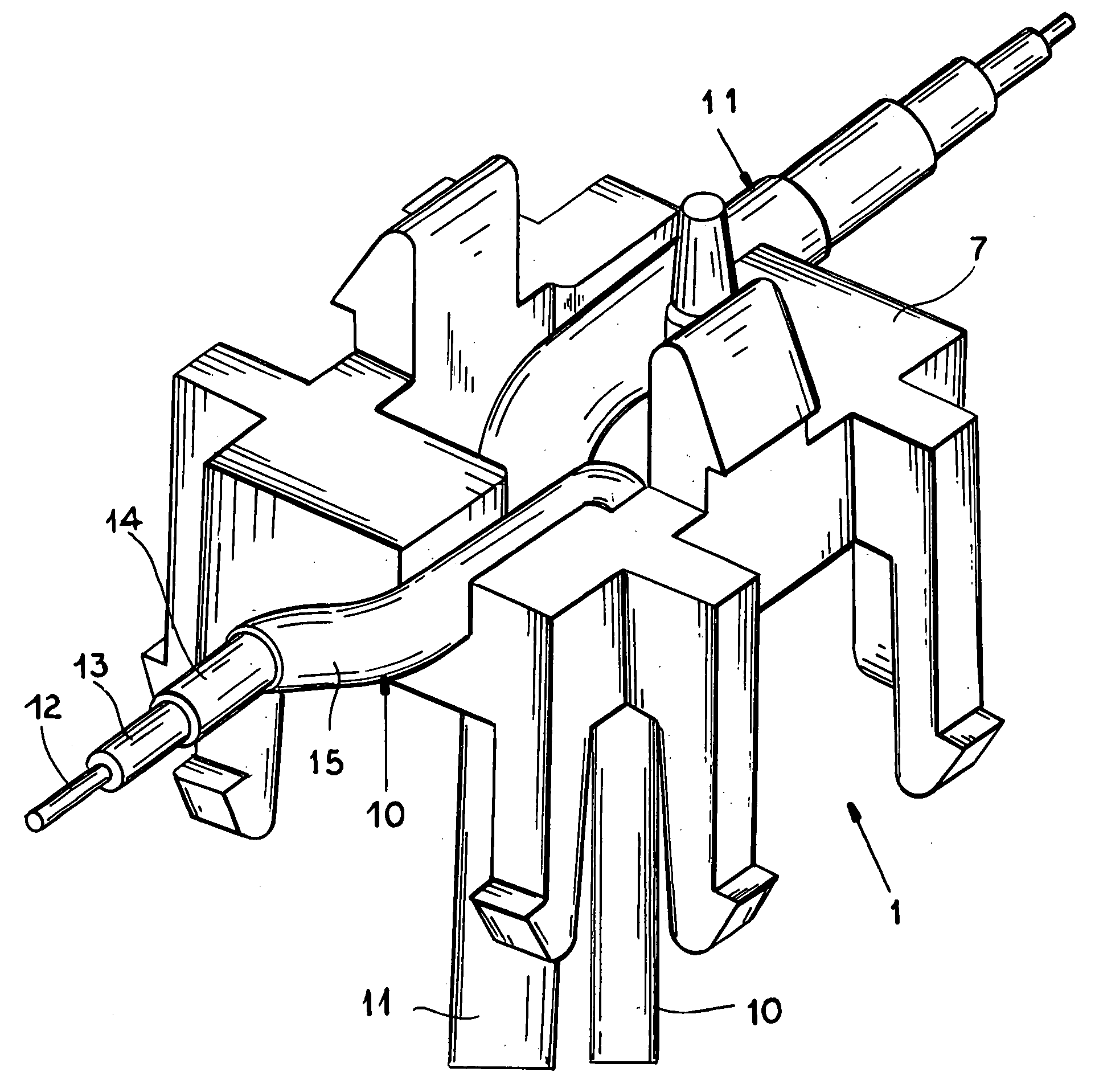
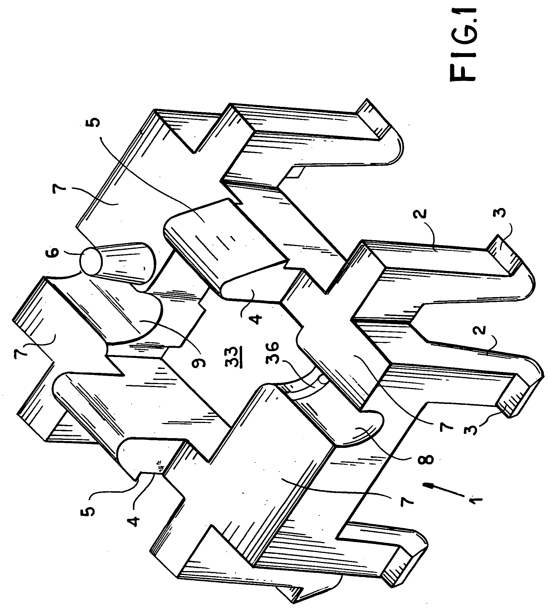
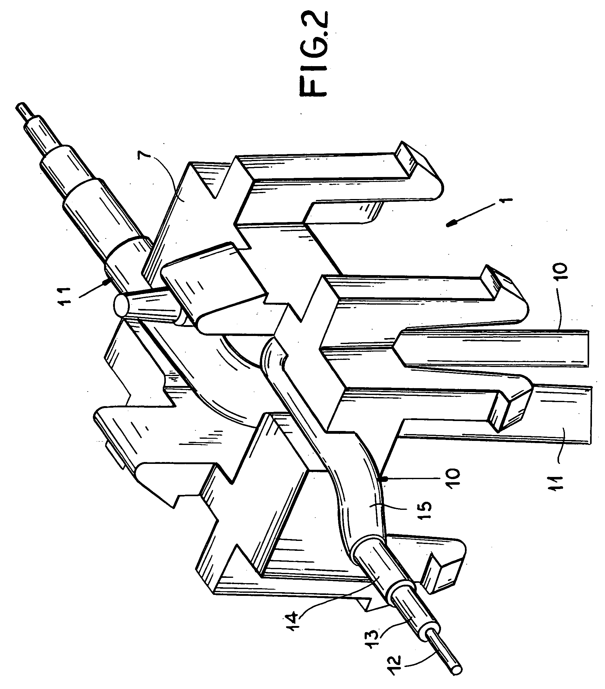
[0022] As seen in FIG. 1 a plastic injection-molded mounting element 1 is a generally rectangular annular frame centrally defining a throughgoing rectangular-section opening 33. It has on each side at the corners two normally downwardly extending legs 2 each having in turn an outwardly extending barb or tooth 3. The element 1 has an upwardly directed planar seat surface 7 from which two legs or projections 4 extend upward and an opposite downwardly directed planar bottom surface 34 that is parallel to the top surface 7. The projections 4 are parallel to each other on opposite sides of the central hole 33 and have oppositely and outwardly directed barbs or teeth 6. An upwardly tapered frustoconical centering pin 6 projects upward from the surface 7 to one side of the two projections 4. The entire element 1 is stiff but slightly elastically deformable. It is formed with two oppositely extending grooves 8 and 9 opening at the surface 7 and of different radii of curvature. One of the gr...


PUM


Abstract

A flat base plate sits atop a motor-vehicle panel and is formed with a mounting pin extending downward through the panel. A flat antenna circuit board sits on the base plate, and a connector cable extends upward through the pin and through the base plate and is connected to the circuit board. A one-piece mounting element is unitarily formed with an upper face and latch legs projecting upward from the upper face and having barb ends latchingly engageable with the circuit board to retain the circuit board on the upper face. It is further unitarily formed with a lower face and latch legs projecting downward from the lower face through the base plate and roof panel and having barb ends latchingly engageable with the roof panel to hold the circuit board and base plate down against the roof panel.

Description

FIELD OF THE INVENTION [0001] The present invention relates to an antenna mount. More particularly this invention concerns a mount for securing an antenna to a motor vehicle. BACKGROUND OF THE INVENTION [0002] As described in copending application Ser. No. 10 / 732,922 filed 10 Dec. 2003, an antenna assembly for mounting upon a wall of a vehicle body has a metallic base plate with a face adapted to be juxtaposed with the vehicle wall. A plastic housing encloses antenna elements mounted on the base plate. A seal between the plate-shaped portion and the wall seals the base plate relative to an interior of the vehicle body. A threaded mounting pin extends downward from the metallic base plate. [0003] Here a cable extends through the base plate to the antenna elements, where it is normally soldered to traces of a circuit board. The circuit board in turn is formed with a plurality of holes matching threaded holes in the base plate so this circuit board can be secured in place by screws. Su...

Claims


Application Information

Patent Timeline
IPC IPC(8): H01Q1/12H01Q1/32
CPCH01Q1/3275H01Q1/1214
Inventor NAGEL, STEFAN
Owner HIRSCHMANN ELECTRONICS GMBH & CO KG
Why Eureka
Try Eureka