Vehicular lamp

Inactive Publication Date: 2005-10-27
KOITO MFG CO LTD
View PDF2 Cites 44 Cited by
  • Summary
  • Abstract
  • Description
  • Claims
  • Application Information

AI Technical Summary

Benefits of technology

[0014] Accordingly, the object of the present invention is to provide a vehicular lamp that involves a luminescent element module or a ci

Problems solved by technology

However, building a circuitry on a hard substrate inevitably tends to restrict the shape of the vehicular lamp to which the circuitry is applied.
In other words, a hard substrate only allows flat placement of electronic components, which is a problem.
Thus, when a light-emitting diode, for example, is used as a light source in place of an incandescent bulb, the light-emitting bulb can only be disposed flatly; and as a result, in vehicular lamps that use hard substrates, the light-emitting diodes are installed only flatly.
However, the FPC becomes exclusive to each vehicular lamp type, and the manufacture of which requires many complicated processes; as a result, since vehicular lamps generally come in a wide variety of types and thus involve limitations in the number of production, vehicle lamps that use the FPC have

Method used


Image

  • Vehicular lamp
  • Vehicular lamp
  • Vehicular lamp

Examples


first embodiment

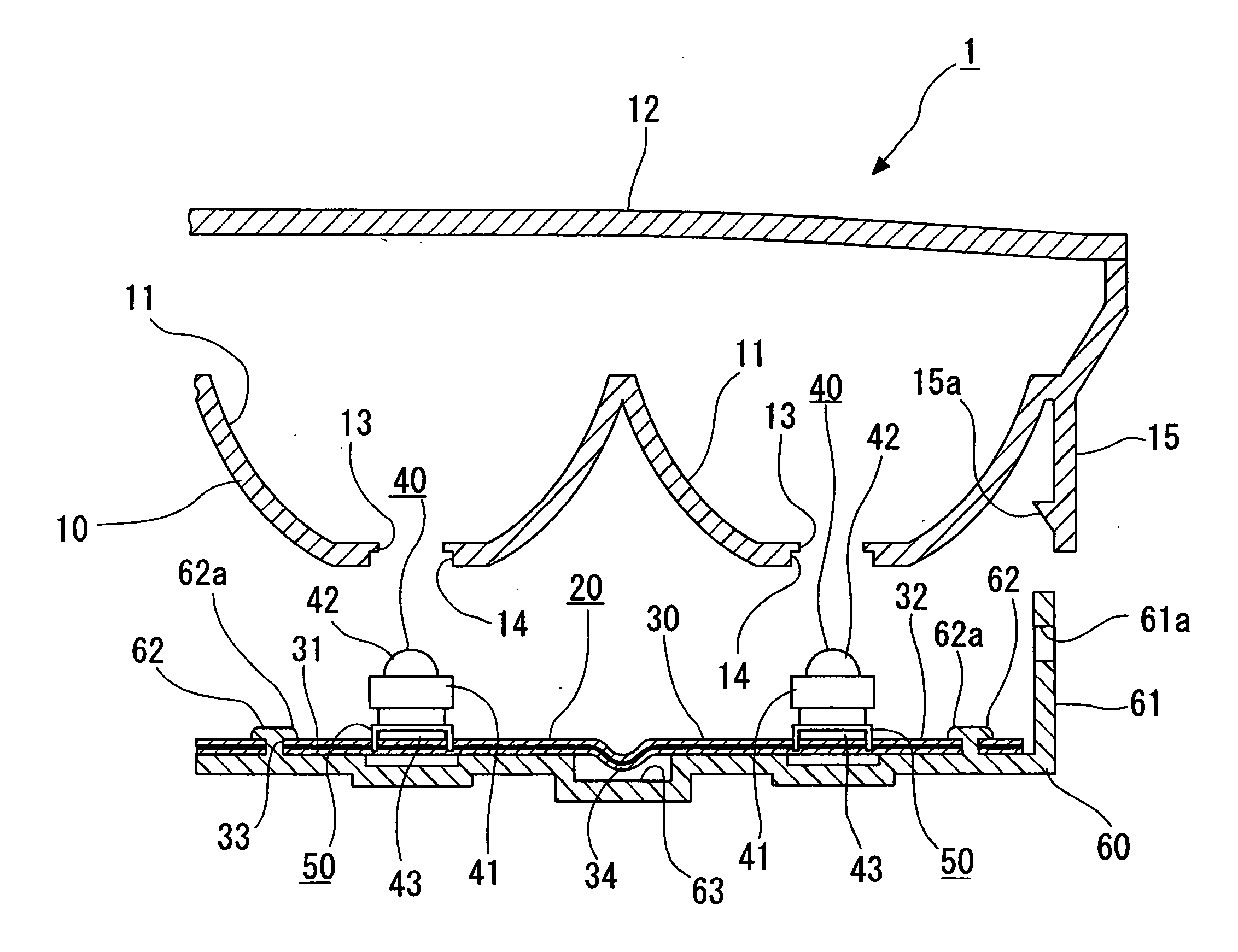
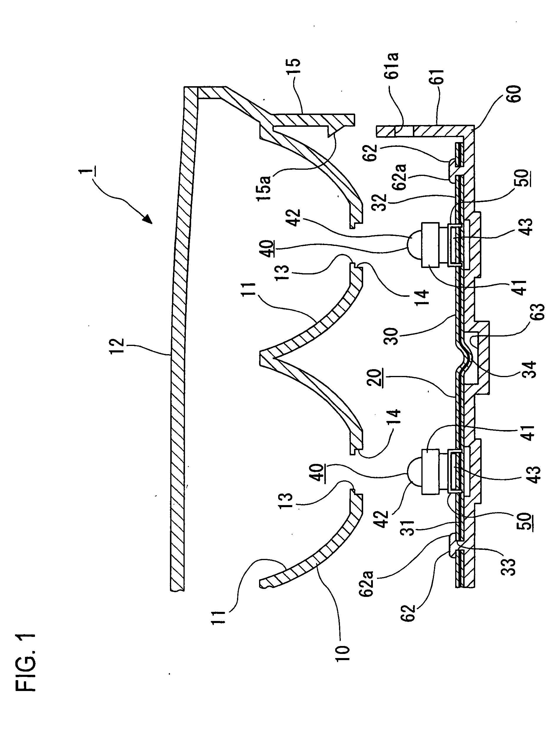
[0036]FIG. 1 shows the vehicular lamp of the present invention.

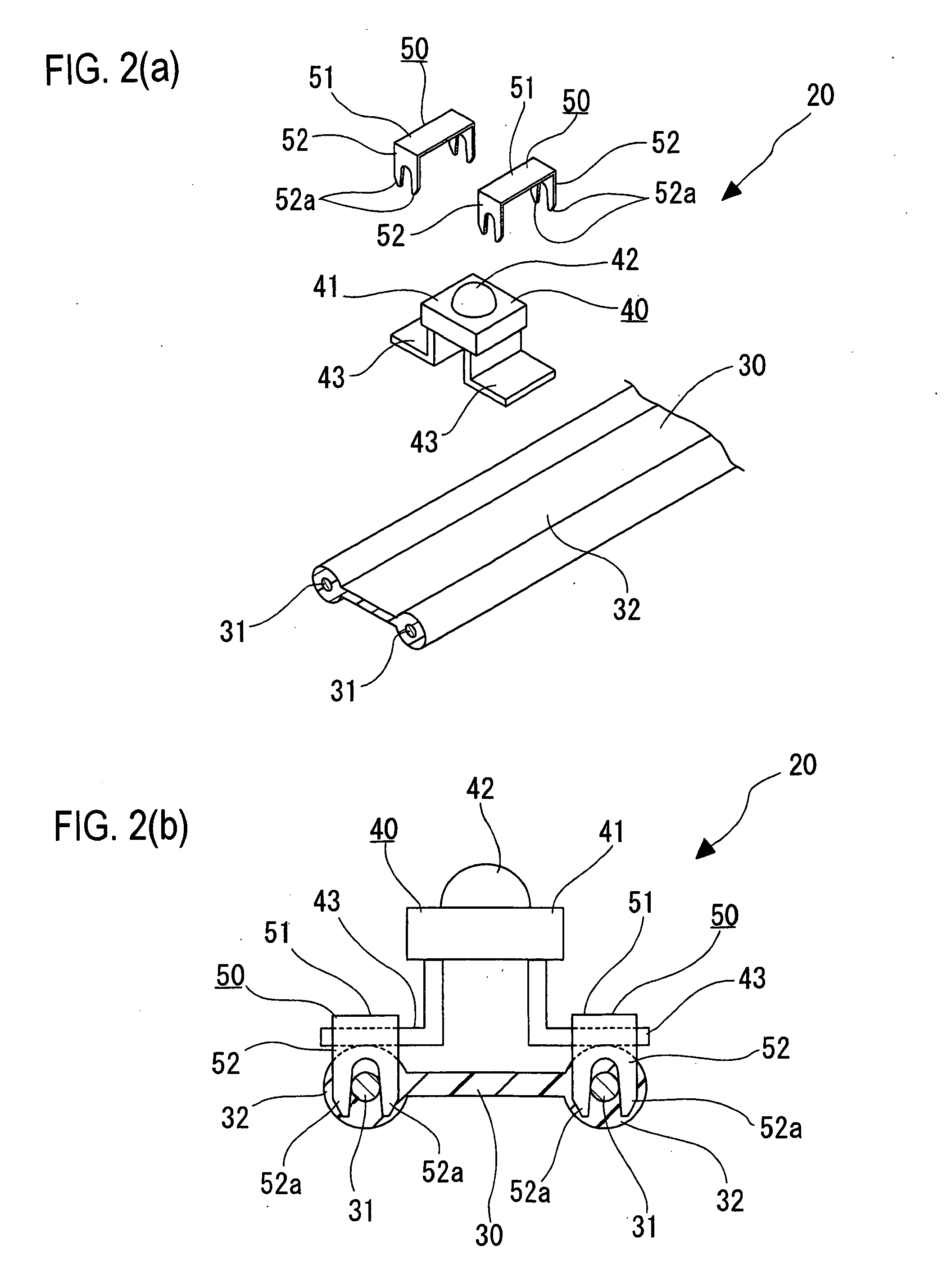
[0037] A vehicular lamp 1 is comprised of a lamp body 10 and a luminescent element module 20 which is provided on the back surface of the lamp body 10.

[0038] On the lamp body 10, a plurality of concave portions 11 (only two of which are shown in FIG. 1) are formed such that the luminescent elements (diodes) of the luminescent element module 20 face forward (upward in FIG. 1). Each of the front surfaces of the concave portions 11 is covered by a cover lens 12. The concave portions 11 open forward, and positioning openings 13 are formed on the rear or bottom end portions. Shallow concave engagement edges 14 are formed on a portion of on the concave portions 11 that surround the rear surfaces of the positioning openings 13. In addition, rear-projecting engaging segments 15 (only one of which is shown in FIG. 1) are formed on the end portions of the lamp body 10 so as to project rearward, and engaging tabs 15a are formed on...

third embodiment

[0060] FIGS. 7(a) through 7(c) show the vehicular lamp according to the present invention. In this embodiment, the light-emitting diodes 40 are provided in a three-dimensional fashion.

[0061] More specifically, the rear portion of the lamp body (and also possibly a reflector) 10C is formed in a stepped configuration so that a plurality of stepped planes 70 are formed and arranged at different levels. Step surfaces 71 connect the stepped planes 70

[0062] Formed on the rear surface of each stepped plane 70 is a shallow concave portion 72 that has a generally rectangular shape. A positioning opening 73 is opened at substantially a central portion of the concave portion 72 so as to extend in the longitudinal direction. Support pins 74 are formed on the rear surface of the stepped plane 70 to project rearward at locations on both sides of the positioning opening 73.

[0063] The luminescent element module 20 is formed with supporting holes 33 at positions sandwiching the light-emitting diode...


PUM


Abstract

A vehicular lamp including a luminescent element module made of a flexible parallel wiring body, which is made of a plurality of flexible wiring conductors that are disposed parallel to each other and sheathed by soft plastic, and a plurality of light-emitting diodes, which are mounted on the flexible parallel wiring body, so that the luminescent element module has a conductive path formed by notching a part of the wiring conductors of the flexible parallel wiring body and/or by connecting a plurality of the wiring conductors together, and the luminescent element module is provided on the lamp body so that the light-emitting diode faces in the direction of radiation of the vehicular lamp.

Description

BACKGROUND OF THE INVENTION [0001] 1. Technical Field [0002] The present invention relates to a vehicular lamp and more particularly to a vehicular lamp that is manufactured at low cost. [0003] 2. Description of the Related Art [0004] Some of the recent vehicular lamps are equipped with circuitries. [0005] For installing a circuitry in a vehicular lamp, the circuitry is formed on a hard substrate or an FPC (Flexible Printed Circuit), and this substrate or an FPC that has the circuitry mounted is installed in a vehicular lamp. [0006] However, building a circuitry on a hard substrate inevitably tends to restrict the shape of the vehicular lamp to which the circuitry is applied. In other words, a hard substrate only allows flat placement of electronic components, which is a problem. Thus, when a light-emitting diode, for example, is used as a light source in place of an incandescent bulb, the light-emitting bulb can only be disposed flatly; and as a result, in vehicular lamps that use ...

Claims


Application Information

Patent Timeline
IPC IPC(8): F21S8/10F21V19/00F21V21/002F21V23/00F21W107/00F21Y101/02H05K1/18H05K3/30H05K3/32
CPCF21S48/212F21S48/215F21V21/002F21Y2101/02H05K1/189H05K2203/1189H05K3/301H05K3/326H05K2201/10106H05K2201/10598H05K2201/10916H05K3/0064F21Y2115/10F21S43/195F21S43/14
Inventor TSUKAMOTO, HIRONORIYAMAMOTO, KAORU
Owner KOITO MFG CO LTD
Why Eureka
Try Eureka