Refueling work platform

a technology for refueling work platforms and work platforms, which is applied in the direction of nuclear engineering problems, greenhouse gas reduction, nuclear elements, etc., can solve the problems of limiting the usefulness of future fuel movement activities, requiring regular maintenance of electric distribution systems and instrument and control systems, and some inherent limitations in their effectiveness, so as to reduce undesirable effects, increase the number of jib hoists mounted on the platform, and enhance the ability

Inactive Publication Date: 2005-10-27
MCCANN JAMES E +2
View PDF10 Cites 3 Cited by
  • Summary
  • Abstract
  • Description
  • Claims
  • Application Information

AI Technical Summary

Benefits of technology

[0013] The Refueling Work Platform of the present invention improves upon the desirable design features of the prior art platforms while eliminating the undesirable. First, the number of jib hoists mounted on the platform is increased. This enhances the ability to perform parallel tasks during in-vessel work. Second, shielding is provided in the Personnel Ring of the platform to reduce the dose rate in the personnel work area. Third, the personnel ring on the Refueling Work Platform is constructed to be raised and lowered. When in the “up” position, the Refueling Work Platform safely passes over all obstructions in the reactor cavity. When in the “down” position, the Refueling Work Platform is low enough to provide clearance for the Refueling Platform and mast to be positioned over the refueling platform. All core locations can thus be accessed by the personnel in the personnel ring of the platform during fuel movement operations.
[0014] The net result of this invention is that the Refueling Work Platform does not need to be disassembled or removed from the rails and stored elsewhere during the head and internals lifts. This frees critical plant resources (crane and floor space) for other uses.

Problems solved by technology

In addition, the electrical distribution systems and the instrument and control (IC) systems require regularly scheduled maintenance.
Both categories of the prior art platforms described above provided some functionality, but also had some inherent limitations to their effectiveness.
Auxiliary Platforms originally supplied during plant construction were of a design that limited their usefulness during future fuel movement activities.
Significant schedule impacts resulted from this limitation in the first “Auxiliary Platform” design.
First, the redesign provided an unobstructed path for the mast on the Refueling Platform and an open area in the interior of the Auxiliary Platform.
Second, the redesign lowered the working elevation of the Auxiliary Platform.
However, the second type of Auxiliary Platform still had inherent weaknesses.
Lowering the working elevation of the platform caused several problems.
First, lowering the working elevation put the workers closer to the radiation source, thus increasing the dose rates in the work area.
Second, the lower working elevation caused interference with reactor cavity structures away from the reactor vessel.
This became an issue at the start and close of an outage during the reactor head and internals (moisture separator and steam dryer) moves.
However, before the platform could be sufficiently moved away from the vessel, the lowered working elevation would interfere with building structures that divided the reactor cavity from the steam dryer and moisture separator storage areas.
With storage space at a minimum, only one crane available, and significant time required for disassembly and reassembly of the platform, removal and replacement of the “Auxiliary Platform” was costly, presented logistical challenges and was ultimately undesirable.
The small size of the work station hampered the worker's productivity.
Fourth, the access path provided for the Refueling Platform mast caused a discontinuity in the structure that weakened the “Auxiliary Platform”.
As a result, additional supports had to be installed in the reactor vessel and / or internals which required additional worker effort and, due to their installation location, fall protection was required.
Additionally, since the supports would be underwater at times, another source for hot particles and other contamination was created.

Method used


Image

  • Refueling work platform
  • Refueling work platform
  • Refueling work platform

Examples


Embodiment Construction

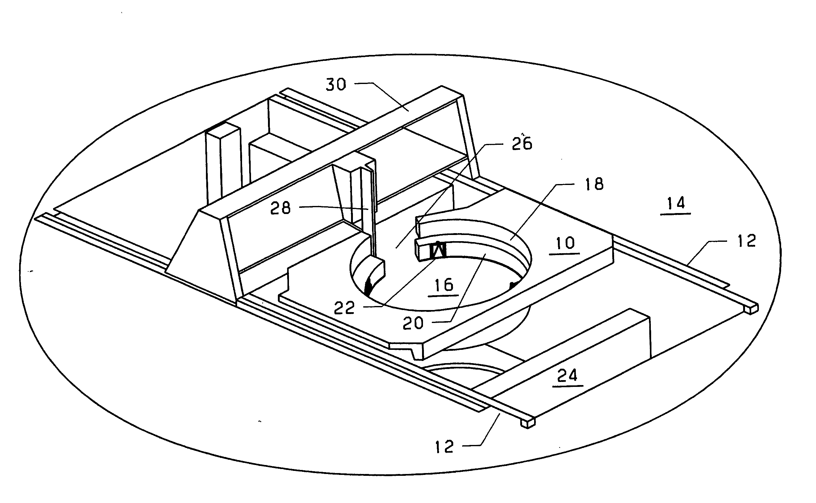
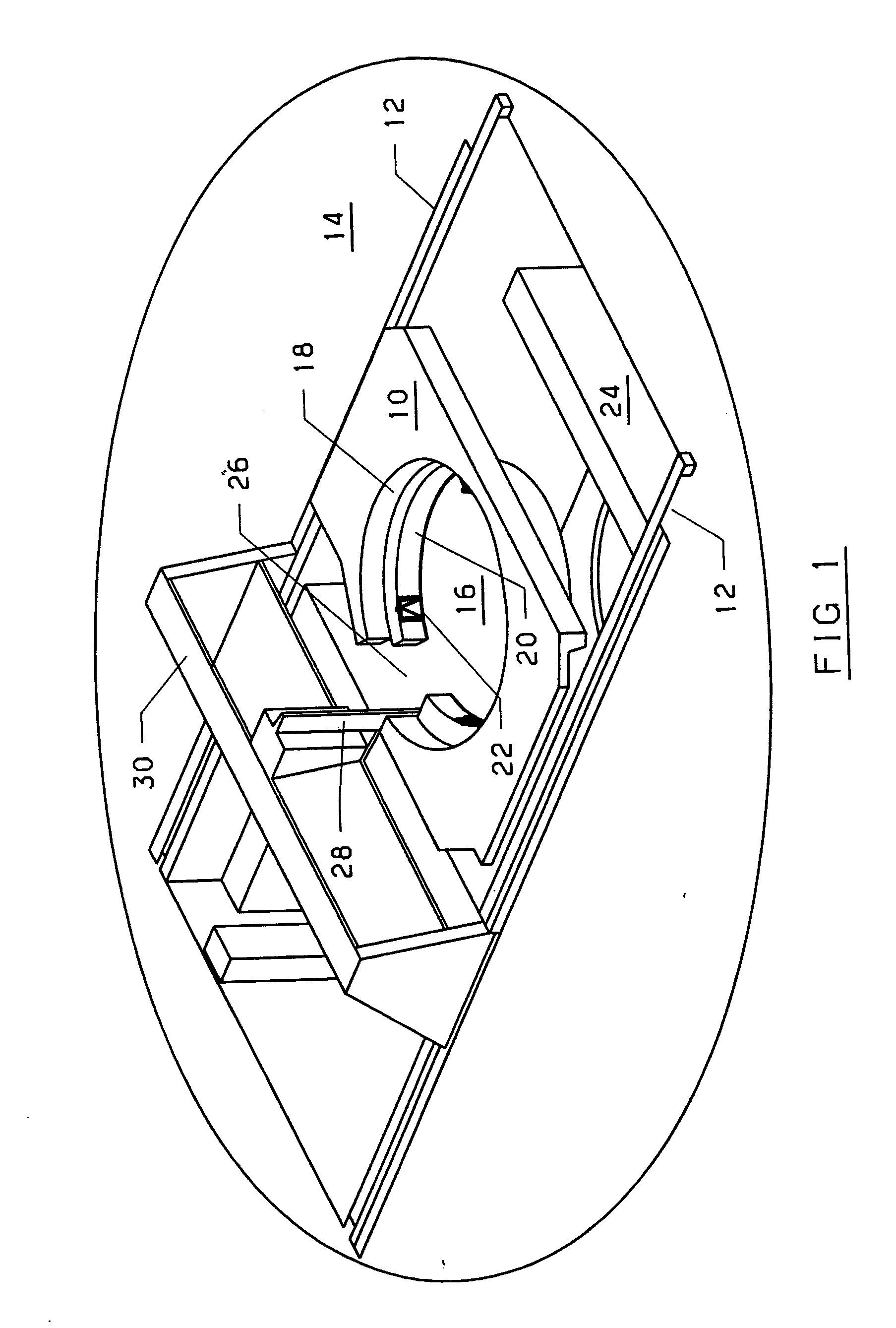
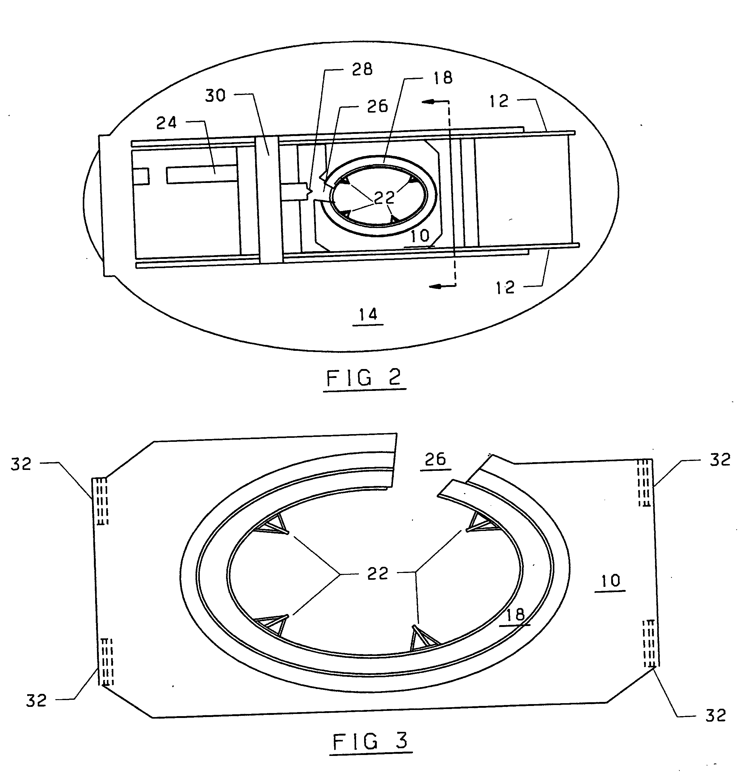
[0031] Referring now to the drawings and FIGS. 1-2 in particular a Refueling Work Platform (10) is shown which is movable on rails (12) already constructed across a reactor cavity (14) for the refueling process. The platform (10) has a central opening (16) having an arcuate personnel ring (18) that comprises a sealed 330 degree area with an open top to maximize the available working area for personnel and provide a larger work area than the prior art platforms. The platform has a radiation shielded wall (20) to protect the personnel from radiation. Mounted on the wall (20) are multiple independent jib hoists (22) having an approximate hoisting capacity of 500 pounds. This enhances the ability for personnel to perform multiple in-vessel tasks in parallel. The platform is designed to be rigid enough that secondary supports from existing reactor cavity structures (24) are not required.

[0032] The platform has a free entry area (26) located at one end of cavity (16) providing access for...


PUM


Abstract

The present invention comprises a refueling work platform for use during reactor refueling operation to allow inspection / repair of the reactor vessel simultaneously with the removal and insertion of fuel cells from and into the reactor due to the personnel ring of the work platform being movable down into the reactor cavity to allow a refueling platform to move over the work platform to provide refueling operations while the personnel on the ring are doing their inspection and repair.

Description

BACKGROUND OF THE INVENTION [0001] 1. Field of the Invention [0002] The present application is generally drawn to refueling work platforms and more particularly to work platforms installed over the reactor cavity during refueling of the reactor which allow in-vessel work to be performed simultaneously with refueling. [0003] 2. Description of the Prior Art [0004] Much of the maintenance performed in nuclear power plants is similar to that for conventional non-nuclear systems. This includes equipment lubrication, fluid level checks and adjustments. Because most of the active systems are fluid (water, steam or air) systems, most of the work is performed on pumps, valves, fans and filters. In addition, the electrical distribution systems and the instrument and control (IC) systems require regularly scheduled maintenance. As previously discussed, nuclear systems are unique in that many components are inaccessible. [0005] The reactor vessel and its internals are static components requirin...

Claims


Application Information

Patent Timeline
Patent Type & Authority Applications(United States)
IPC IPC(8): G21C17/00G21C19/00G21C19/20
CPCG21C17/00G21C19/20G21Y2002/301G21Y2004/40G21Y2002/402G21Y2004/30G21Y2002/304Y02E30/30
Inventor MCCANN, JAMES E.LOVAS, ALBERT J.RAY, MELANIE S.
Owner MCCANN JAMES E
Why Eureka
Try Eureka