

Fluid level control system
a level control and control system technology, applied in the direction of pump control, positive displacement liquid engine, construction, etc., can solve the problems of not producing at maximum, not maximizing production revenues, and damage to pumps, so as to reduce power output, reduce power output, and reduce power output. effect of prime mover power outpu
- Summary
- Abstract
- Description
- Claims
- Application Information
AI Technical Summary
Benefits of technology
Problems solved by technology
Method used
Image

Examples
example 1
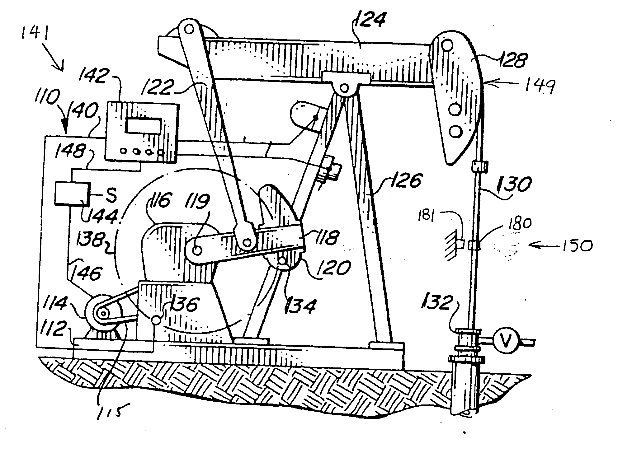
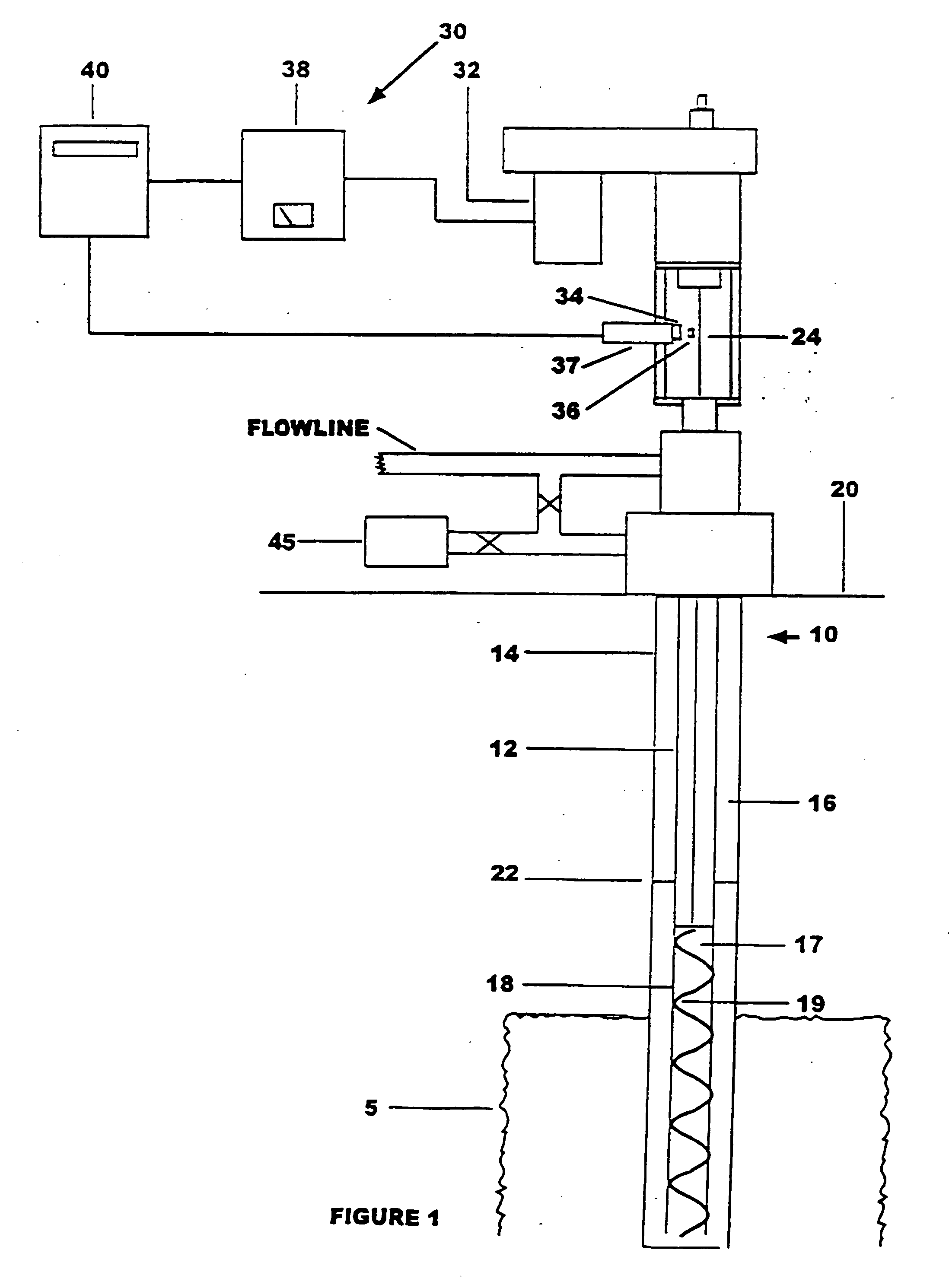
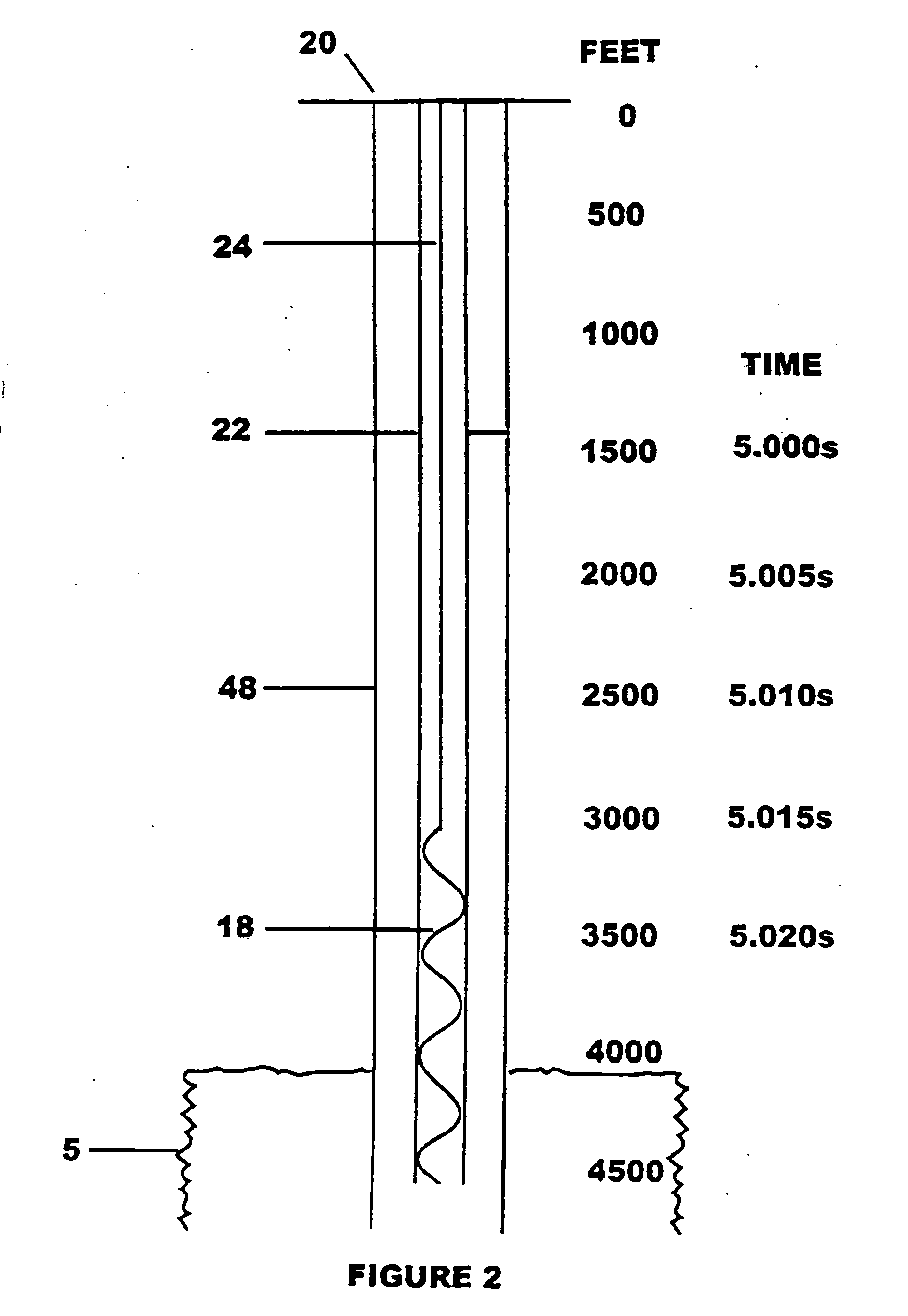
[0027] The prime mover has an upper and lower power setting. The controller is set up to measure a time interval for 30 rod revolutions. Using an ultrasonic level detector to calibrate the well, the “optimum” fluid level is predetermined to be 300 feet, at which the rod rotation rate is 400 RPM. For 30 revolutions at 400 RPM (optimum), the time interval is 4.5 seconds (4500 ms). Thus, one value in the data set is the time interval of 4500 ms. Similarly, the maximum fluid level corresponds to a time interval of 4520 ms and the minimum fluid level corresponds to 4480 ms (a time difference “delta-t” of + / − 20 ms). These values may also be programmed into the controller. After calibration, the control system is ready for operation. The controller will “know” to decrease power when the time interval rises above 4520 ms and increase power when the time interval drops below 4480 ms. For instance, if the prime mover is operating at the lower power setting and the measured time interval reac...
example 2
[0043] The motor 114 has an upper and lower power setting. Using an ultrasonic level detector to calibrate the well, the maximum fluid level is determined to correspond to a time interval of 5090 ms and the minimum fluid level corresponds to 6010 ms (a dT of + / − 20 ms). These values are programmed into the control system 110. During subsequent operation of the well system 150, the motor 114 may be turned on, and the control system 110 notes as signaled the time interval required for each full cycle of the rod 130 (or fraction thereof). The control system selects one of the time intervals as a reference time interval—preferably the first time interval (or one of the first several time intervals) computed after turning the motor on. The control system compares subsequent computed time intervals with the reference time interval. The motor 114 continues to run and the control circuitry 142 continues to compute time intervals until the control system 110 has detected an increase of at le...
example 3
[0044] As in Example 2, the motor 114 has an upper and lower power setting. Using an ultrasonic level detector to calibrate the well, the maximum fluid level is determined to correspond to a time interval of 5090 ms and the minimum fluid level corresponds to 6010 ms. These two time intervals are programmed into the control system 110. In contrast to Example 2, however, dT is not recorded. During subsequent operation of the well system 150, the motor 114 may be turned on to the same upper power setting used to calibrate the well. The control system 110 computes the time interval required for each full cycle (or fraction thereof) of the rod 130. The motor 114 continues to run and the control circuitry 142 continues to compute time intervals until the control system 110 has detected a time interval greater than or equal to 6010 ms, indicating the fluid has reached the lower fluid level 154. Then the control system 110 decreases power to the motor 114 to a lower power setting, such that...
PUM
 Abstract
Description
Claims
Application Information