Radio access line extending device
- Summary
- Abstract
- Description
- Claims
- Application Information
AI Technical Summary
Benefits of technology
Problems solved by technology
Method used
Image

Examples
first embodiment
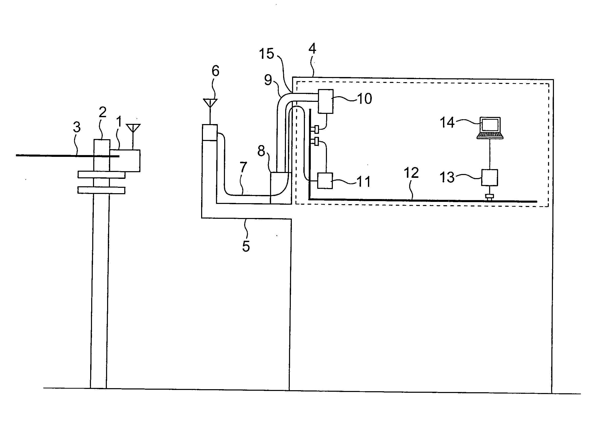
[0016]FIG. 1 is a structural diagram showing a subscriber radio access line extending device according to a first embodiment of the present invention. As shown in FIG. 1, the subscriber radio access line extending device according to this embodiment is equipped with a subscriber outdoor device 6 that conducts radio communication with a radio base station 1 which is placed on an electric pole 2 and connected to an external communication line 3. The subscriber outdoor device 6 is located on a veranda 5 of a collective housing 4. The subscriber outdoor device 6 is connected with a feeder Ethernet cable 7 (hereinafter referred to as “feeder LAN cable 7”) which is connected to an indoor electric lamp wire 12 through a subscriber media converter 11. In recent years, there are many cases in which an outdoor device 8 for an air conditioner is located on the veranda 5, and a drain pipe 9 (duct) is used to connect the outdoor device 8 and an air conditioner 10 that is located indoors. For tha...
second embodiment
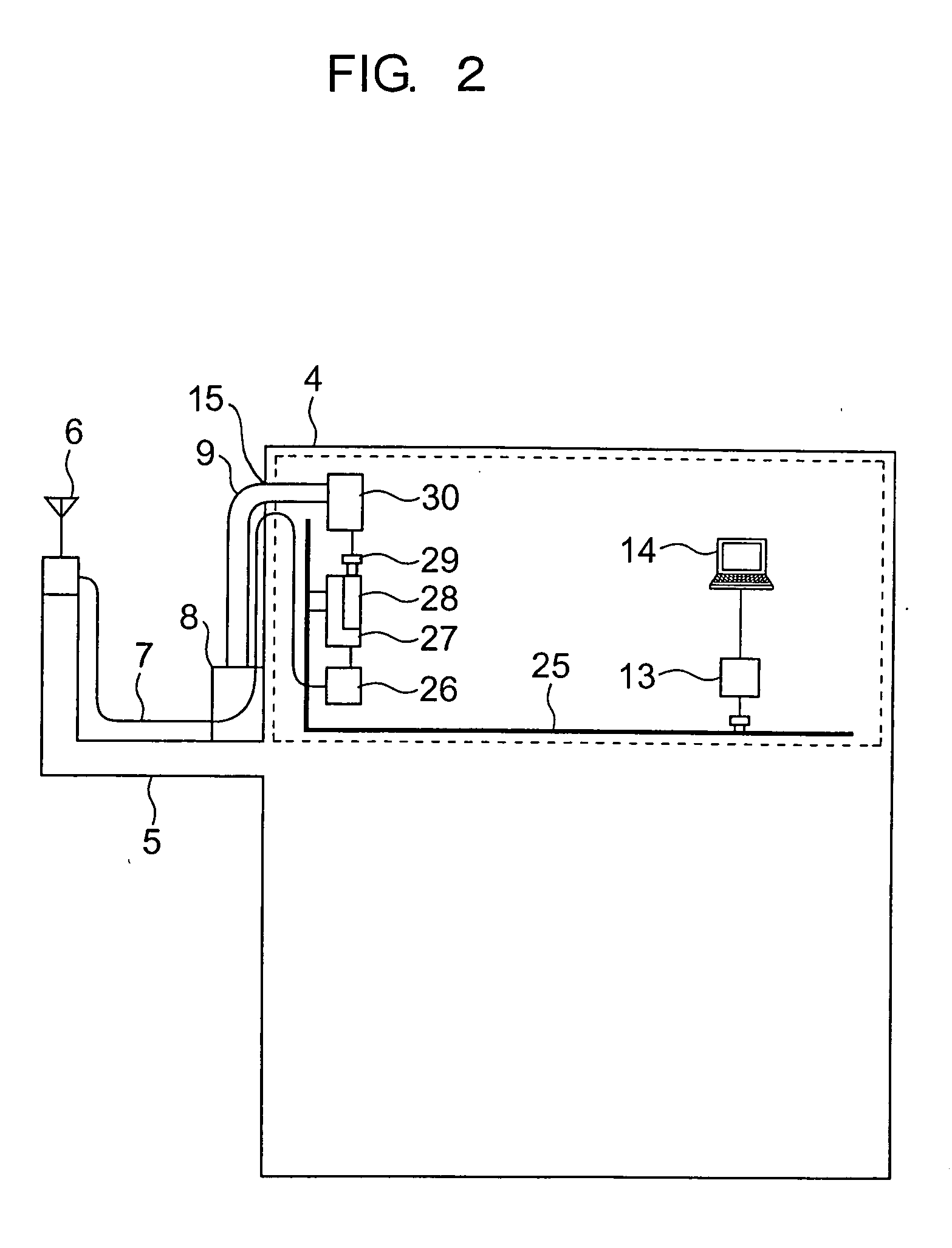
[0019]FIG. 2 is a structural diagram showing the structure of a subscriber radio access line extending device according to a second embodiment of the present invention, which is different from the above-mentioned first embodiment in that a subscriber media converter and an air conditioner are connected to an indoor electric lamp wire through a common mains connector 27 having a noise filter. The same structures as those in FIG. 1 are designated by identical marks, and their description will be omitted hereinafter.
[0020] In the subscriber radio access line extending device according to the second embodiment, as shown in FIG. 2, the subscriber media converter 26 is connected to the indoor electric lamp wire 25 by the mains connector 27 having a noise filter 28. The mains connector 27 with the noise filter 28 has the noise filter 28 built-in. The air conditioner 30 is connected to the indoor electric lamp wire 25 through the mains connector 27 having the noise filter 28 by the power c...
third embodiment
[0023] Subsequently, a description will be given of a subscriber radio access line extending device according to a third embodiment of the present invention.
[0024] In recent years, there arises a problem of the security of radio communication. For example, in a radio LAN of 2.4 GHz, a communication data encrypting system that is called “WAP (wire equivalent privacy)” is normally employed. The power line communication in turn raises a problem of security since a plurality of users conduct communication by means of a common electric lamp wire. A method that solves the above problem and allows a subscriber to readily conduct the setting of security on a device will be described with reference to the third embodiment. The structure of the subscriber radio access line extending device according to the third embodiment will be omitted from description because of the same structure as that of the above-mentioned first or second embodiment. Also, in the following description, an example in...
PUM
 Abstract
Description
Claims
Application Information
 - Generate Ideas
- Intellectual Property
- Life Sciences
- Materials
- Tech Scout
- Unparalleled Data Quality
- Higher Quality Content
- 60% Fewer Hallucinations
Browse by: Latest US Patents, China's latest patents, Technical Efficacy Thesaurus, Application Domain, Technology Topic, Popular Technical Reports.
© 2025 PatSnap. All rights reserved.Legal|Privacy policy|Modern Slavery Act Transparency Statement|Sitemap|About US| Contact US: help@patsnap.com