Wiggle stepper

Inactive Publication Date: 2005-10-27
LIN KUAN I
View PDF3 Cites 14 Cited by
  • Summary
  • Abstract
  • Description
  • Claims
  • Application Information

AI Technical Summary

Benefits of technology

[0008] To achieve the objective, the wiggle stepper in accordance with the present invention comprises a a base member, an adjust seat mounted on the base member, two platforms respectively pivotally mounted to the base member, a connector for connecting the platform and a cylinder that is mounted between the platform and the base mem

Problems solved by technology

As a result, the user may feel that is a boring exercise and gradually reduce the use frequency of the conventional stepper.
In addition

Method used


Image

  • Wiggle stepper
  • Wiggle stepper
  • Wiggle stepper

Examples


Example

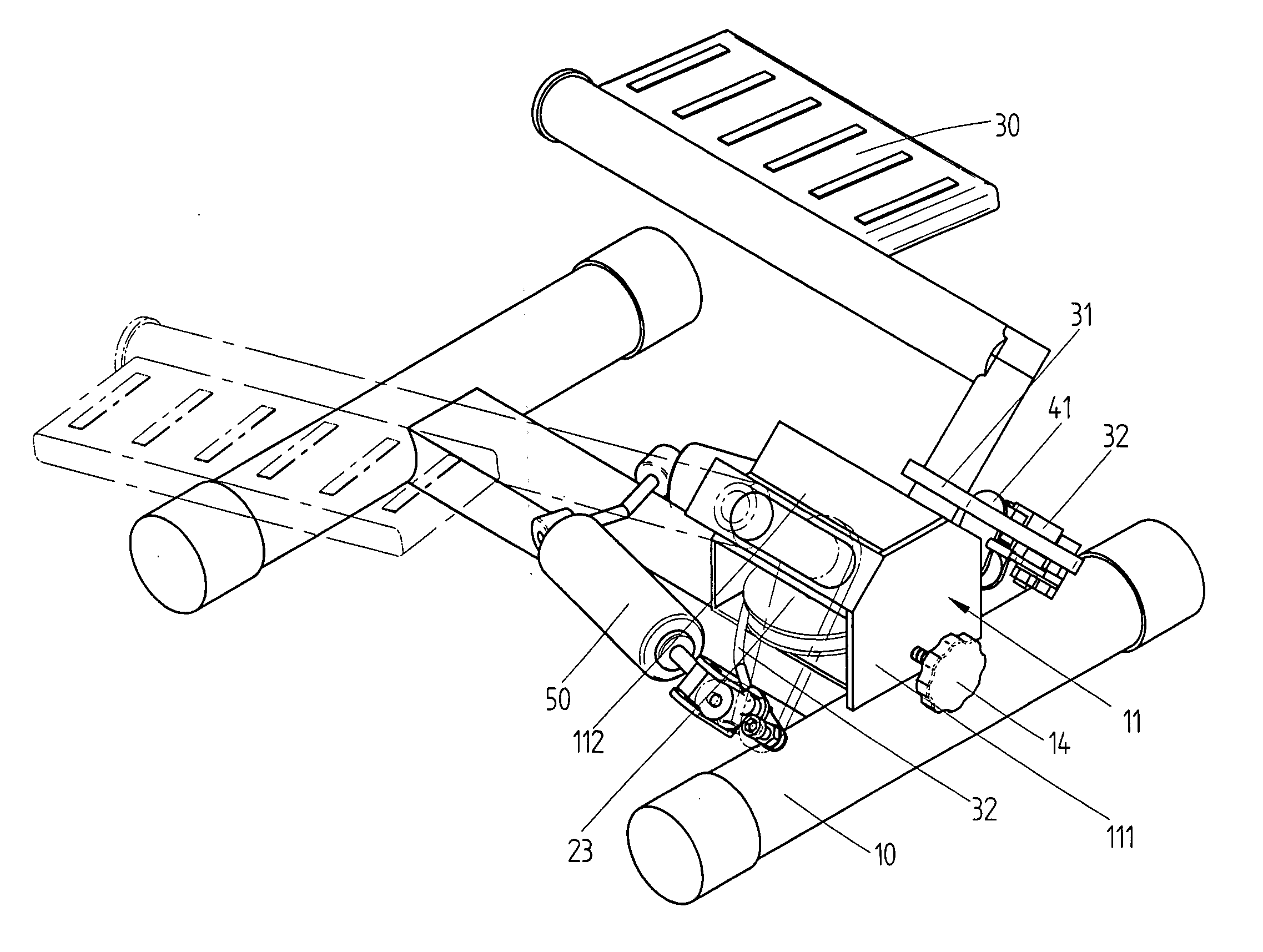
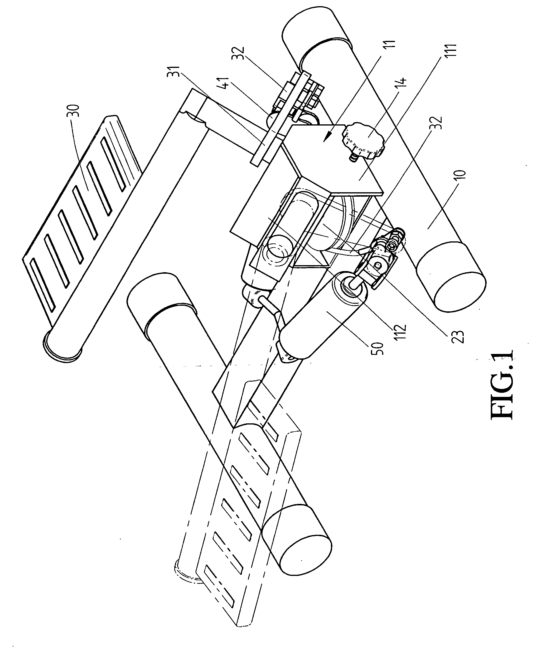
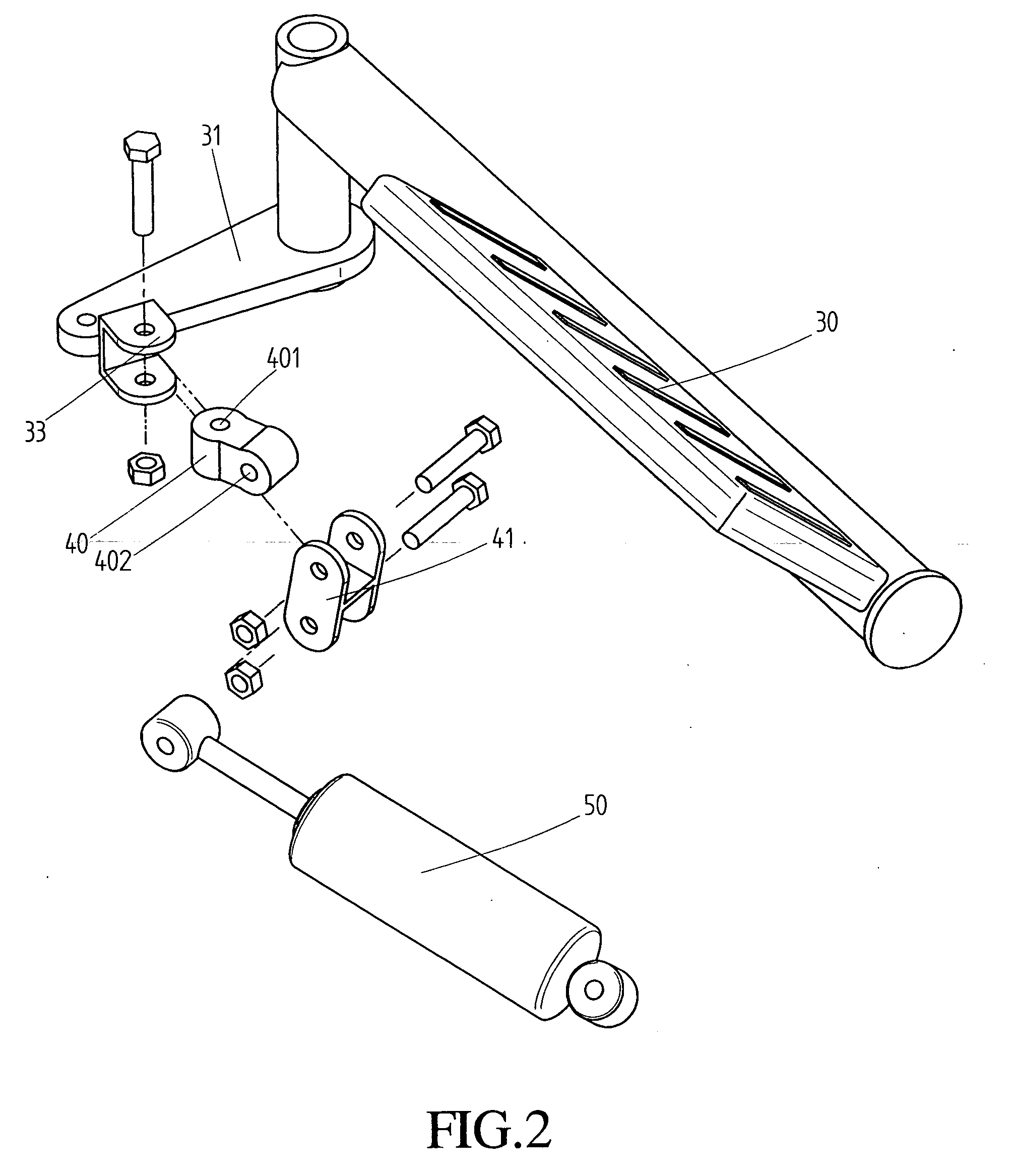
[0019] Referring to the drawings and initially to FIGS. 1-7, a wiggle stepper in accordance with the present invention comprises a base member (10), an adjust seat (20) mounted on the base member (10), two platforms (30) respectively pivotally mounted to the base member (10), a connector (40) for connecting the platform (30) and a cylinder (50) that is mounted between the platform (30) and the base member (10).

[0020] The base member (10) is H-shaped and has a seat (11) mounted on a front portion of the base member (10). The seat (11) includes a plate (111) perpendicularly upwardly secured on a front end of the base member (10) and two cubic posts (112) mounted on a top of the plate (111). The two cubic posts (112) are adjacent and parallel to each other, and extend toward a rear end of the base member (10) to define a V-shaped groove (12) under the two cubic posts (112). Each cubic post (112) includes a front end having a pivot (13) upwardly and outwardly mounted thereon. A bolt (1...


PUM


Abstract

A wiggle stepper includes a base member, an adjust seat mounted on the base member, two platforms respectively pivotally mounted to the base member, a connector for connecting the platform and a cylinder that is mounted between the platform and the base member. Each platform is moved upwardly and downward, and wiggled obliquely to prevent the moving route of the platform from forming a dead space for user to smoothly operate the two platforms. The user can adjust the position of the adjust seat for adjusting the tension from the adjust seat according to the physical strength of the user.

Description

BACKGROUND OF THE INVENTION [0001] 1. Field of the Invention [0002] The present invention relates to a stepper, and more particularly to a wiggle stepper. [0003] 2. Description of Related Art [0004] A conventional stepper in accordance with the prior art shown in FIG. 9 comprises a base member (60) and two platforms (61) each with one pivotally mounted to the base member (60). Two cylinders (62) each mounted between a corresponding one of the two platforms (61) and the base member (60) for providing damping to the two platforms (61) when the user steps thereon. [0005] The conventional stepper only provides an exercise to the user's legs by repeatedly swinging up and down. As a result, the user may feel that is a boring exercise and gradually reduce the use frequency of the conventional stepper. In addition, the damping from the cylinders (62) can not be adjusted according to the purpose of the user. Consequently, the using scope is limited. [0006] The present invention has arisen to...

Claims


Application Information

Patent Timeline
IPC IPC(8): A63B22/04
CPCA63B21/0083A63B2022/0074A63B22/0069A63B21/0087
Inventor LIN, KUAN-I
Owner LIN KUAN I
Why Eureka
Try Eureka