Integrated HVACR control and protection system

a protection system and control device technology, applied in the field of integrated hvacr control and protection system, can solve the problems of reducing efficiency, reducing efficiency, reducing efficiency, etc., and requiring cumbersome access to determine and adjust limits or other aspects of parameters stored by the control devi

Active Publication Date: 2005-10-27
TECUMSEH PROD CO
View PDF23 Cites 96 Cited by
  • Summary
  • Abstract
  • Description
  • Claims
  • Application Information

AI Technical Summary

Benefits of technology

The control and protection system described in this patent monitors various parameters like real power, voltage, current, and temperature to diagnose and prevent problems with an air conditioning system. This allows it to detect issues related to refrigerant pressure drop or blockage without necessarily needing sensors designed specifically for those tasks. Instead, the system measures these factors along with others to determine how well the system is functioning and take appropriate action to keep it running efficiently.

Problems solved by technology

The technical problem addressed in this patent is how to improve the detection and repair of failures in HVACR systems without having to fully shut them down due to the time required for physical inspection. Additionally, it seeks to make more efficient use of limited space when accessing and adjusting parameter settings on control devices.

Method used


Image

  • Integrated HVACR control and protection system
  • Integrated HVACR control and protection system
  • Integrated HVACR control and protection system

Examples


second embodiment

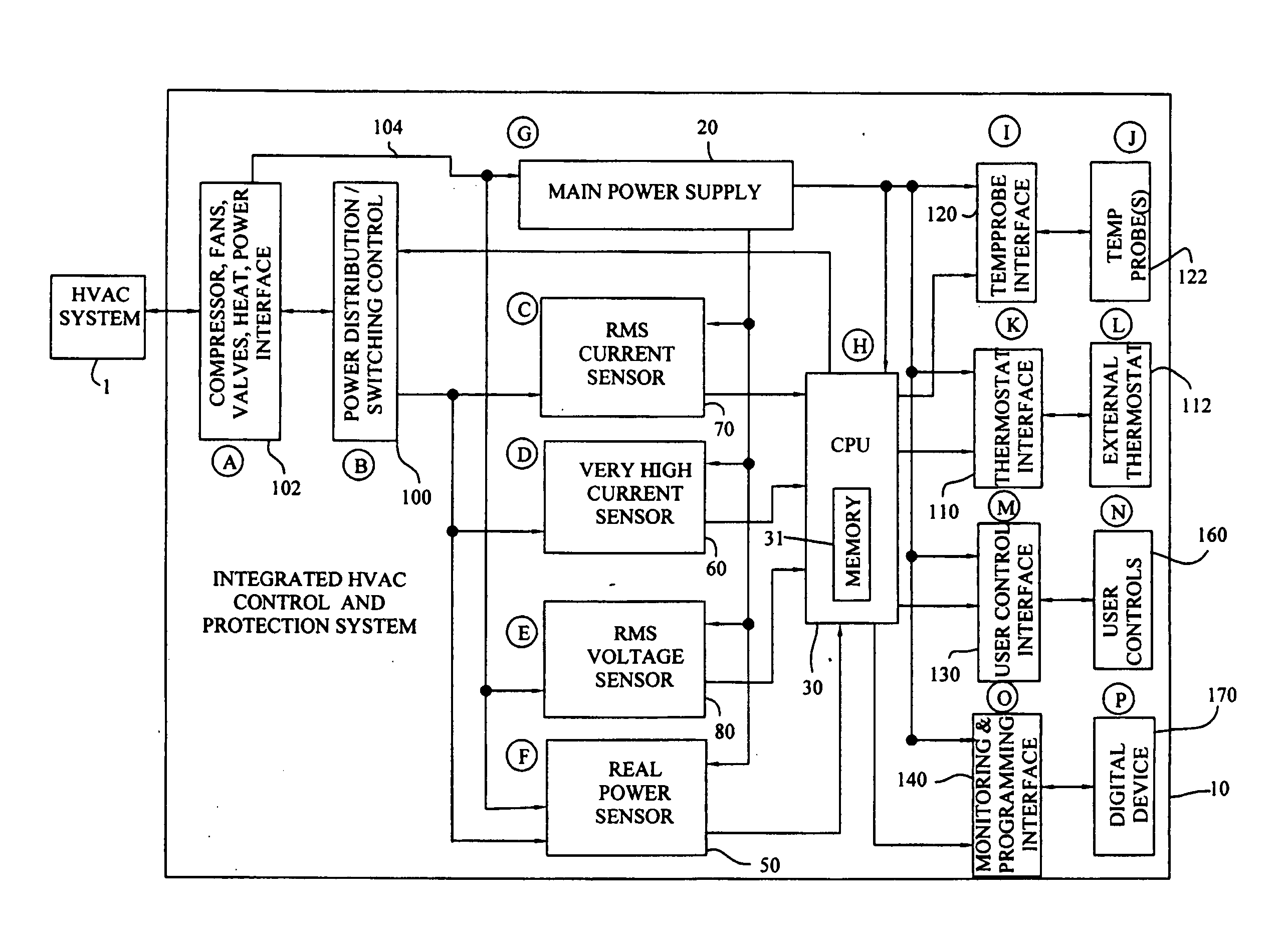
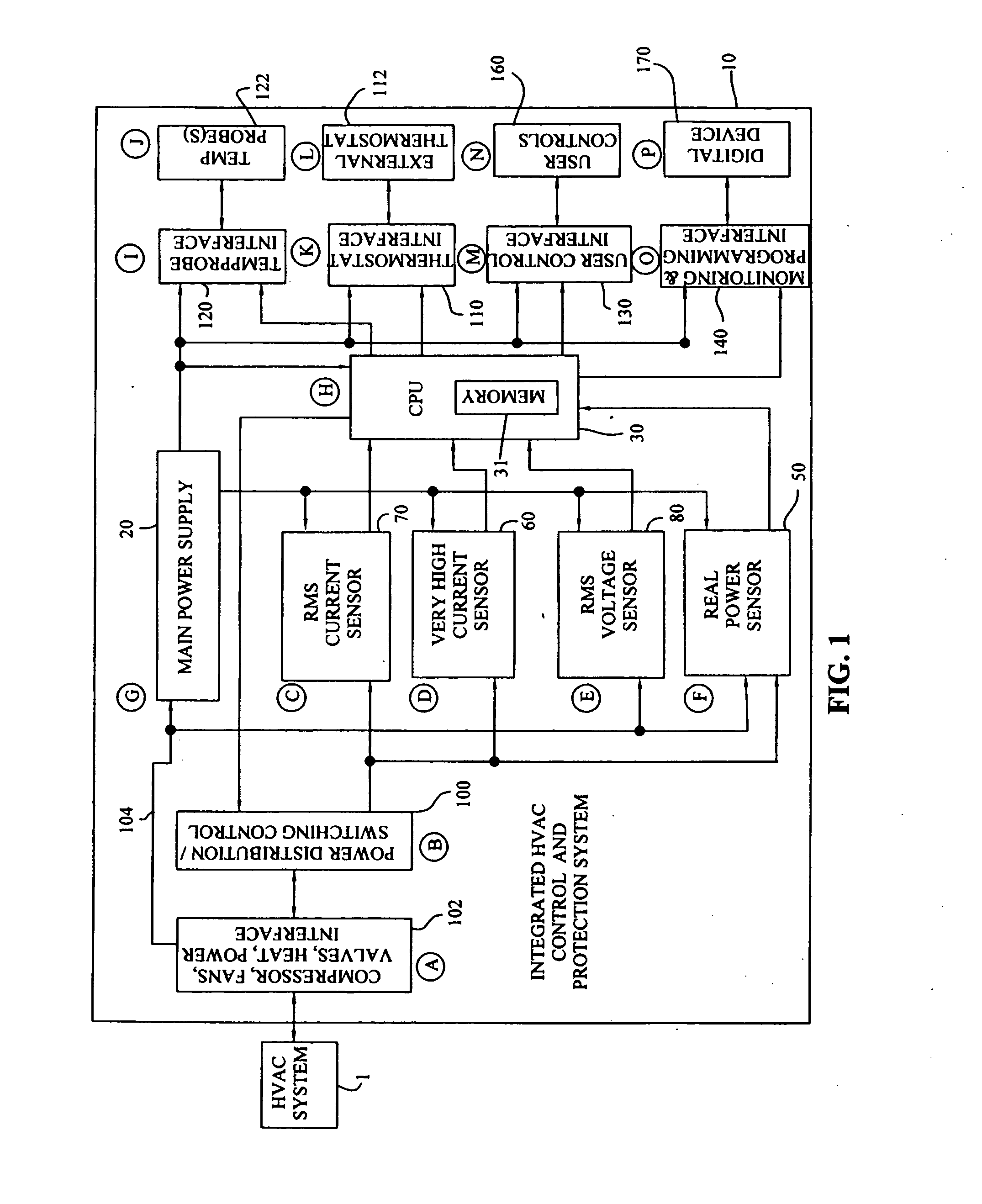
[0068] Referring to FIG. 3, control system 10 is coupled to second embodiment of HVACR control system 301, which is arranged as a refrigeration system, such as an industrial refrigerator having a refrigerator and a freezer compartment. Similar to the second exemplary embodiment of control system 10, control system 10 also includes microcontroller 30 (FIG. 1) and various selected modular subsystems for controlling and protecting HVACR system 301. For example, control system 10 includes temperature sensor interface 120 (FIG. 1) for interfacing microcontroller 30 with defrost sensor 324, refrigerator thermistor 326, and freezer thermistor 328. Control system 10 also includes user control interface 130 and user display and control 160 and control interfaces 140 and digital device 170 for monitoring and programming HVACR system 301.

[0069] Control system 10 may also include one or more electrical sensor circuits 50, 60, 70 and 80 (FIG. 1), for detecting and protecting HVACR system 301 com...

third embodiment

[0070] Referring to FIG. 4, control system 10 is coupled to a third exemplary embodiment of display case system 401 which is configured as a display case refrigerator or freezer system. Similar to HVACR system 301, HVACR system 401 may be controlled and components of the system protected by control system 410. Additionally, HVACR system 401 may include light 460, which is powered by control system 410 and controlled by microcontroller 30. For example, light 460 may be turned on and off based on certain parameters, such as the time of day. Advantageously, user display and control 160″ may be remotely located from control system 10. Specifically, control system 10 may be located inside the display case housing (not shown) and to facilitate access, user display and control 160″ may be located on an exterior portion of the display case housing.

[0071] One exemplary display case display and control 160″, shown in FIG. 22, includes LCD display 181, temperature adjust switches 182, light an...


PUM


Abstract

An integrated HVACR control and protection system includes a modular and reprogrammable design providing a plurality of possible combinations of power detection, voltage detection, run current detection, transient current detection, temperature detection, universal thermostat interface, peripheral or remote control, and local display and control. The control and protection system is capable of evaluating the relationship between real power used by an HVACR system compressor and other system operating parameters to detect problems early in the failure cycle, i.e., before a failure has progressed to requiring a system shutdown or causing damage to other components. Additionally, a control system and method provide sensorless detection of various HVACR system faults, such as, for example, loss of refrigerant or a refrigerant flow restriction, that impact the relationship between real power and current, voltage, temperature, or other operating parameters. Peripheral or remote control includes wired or wireless system monitoring and parameter programming using a personal digital assistant (PDA), for example utilizing IR communication between the PDA and the control and protection system.

Description


Claims


Application Information

Patent Timeline
Owner TECUMSEH PROD CO
Why Eureka
Try Eureka