Restoration mechanism for network topologies

a network topology and restoration mechanism technology, applied in error detection/correction, redundancy hardware error correction, instruments, etc., can solve the problems of large structure size, unsuitable for very large structures, and current use of ethernet switches

Inactive Publication Date: 2005-10-27
METRO PACKET SYST
View PDF4 Cites 23 Cited by
  • Summary
  • Abstract
  • Description
  • Claims
  • Application Information

AI Technical Summary

Benefits of technology

[0005] The system of the present invention provides a solution to the above-outlined problems. More particularly, the method of the present invention is for restoring a failure in a network topology. A first node is provided that has a first access link connected to a first port group of a first customer and a first network link connected to a first active router. A second node has a first access link connected to the first port group of the first customer and a first network link connected to a second stand-by router. The first node has a second network link connected to second node via a second network link. If the first access link of the first node or the first node itself fails, the second node switches to the active state. If the second network link of the first node fails, the second node switches to the active state. In this way the traffic will be securely forward to the first router and / or the second router.

Problems solved by technology

The Ethernet switches currently used in many metro access networks are usually built for corporate environments and are not suitable for very large structures.
The automatic features of most Ethernet switches severally limit the structure sizes that are suitable to be used in connection with the Ethernet switches.
The currently used Ethernet switches are also prone to malfunction when over-loaded since the switches tend to memorize the addresses that have been previously switched.

Method used


Image

  • Restoration mechanism for network topologies
  • Restoration mechanism for network topologies
  • Restoration mechanism for network topologies

Examples


Embodiment Construction

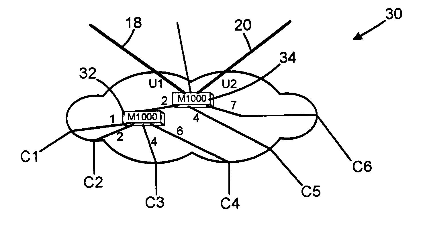
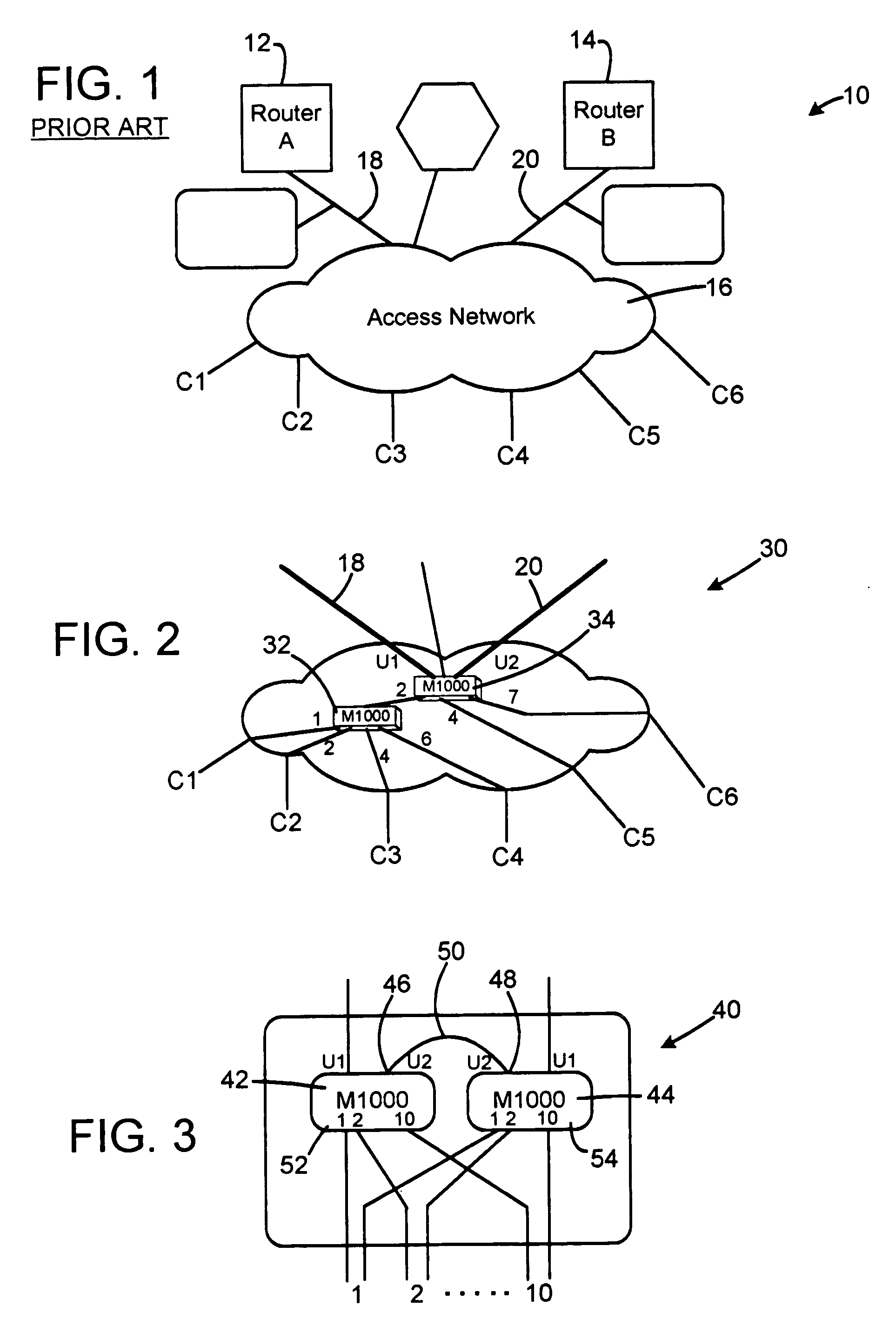
[0020] As shown in FIG. 2, the physical topology 30 may be different than the logical hub and spoke. First, a tree structure may be used to aggregate the customer traffic in several steps towards the hub node. A daisy-chain of Marvin multiplex units 32, 34 can be used to simplify the build out when a tree is unsuitable or to reduce the amount of fiber or copper links as well as the number of router or switch interfaces. The units 32, 34 can be used to connect and merge a plurality of customer lines while keeping each customer line separate with mTags so the traffic to and from the different customers are not mixed up. For example, each unit may have ten customer ports and two network links. The units 32, 34 may have the characteristics of receiving and sending Ethernet frames and the units only switch information between the access ports and the network ports and vice versa but not between different access ports and between different network ports. The tags are used to distinguish t...


PUM


Abstract

A method of restoring a failure in a network topology. A first node is provided that has a first access link connected to a first port group of a first customer and a first network link connected to a first active router. A second node has a first access link connected to the first port group of the first customer and a first network link connected to a second stand-by router. The first node has a second network link connected to the second node via a second network link of the second node. If the first access link of the first node or the first node itself fails, the second node switches to the active state. If the second network link of the first node fails, the second node switches to the active state. In this way the traffic will be forward to the first router and/or the second router.

Description

PRIOR APPLICATION [0001] This is a continuation-in-part application of U.S. patent application Ser. No. 10 / 707,916 filed 23 Jan. 2004.TECHNICAL FIELD [0002] The present invention relates to a protection and restoration mechanism used in network topologies such as faults related to internal link and node failures in access networks associated with, for example, VLAN. BACKGROUND AND SUMMARY OF INVENTION [0003] The logical topology of the infrastructures built of Marlin node units is always hub and spoke. All traffic is back-hauled to the hub and there is no possibility of traffic passing between two access interfaces without passing the router or switch that constitutes the hub. The prior art infra-structure 10 in FIG. 1 shows routers 12, 14 connected to an access network 16 that are associated with customers C1-C6 that may be companies that in turn are connected to internal networks. The network 16 may be a metro access system that has a plurality of Ethernet switches that are suitab...

Claims


Application Information

Patent Timeline
Patent Type & Authority Applications(United States)
IPC IPC(8): G06F11/00G06F15/16
CPCH04L45/00H04L45/22H04L45/28H04L49/557H04L49/351H04L49/354H04L45/58
Inventor ORAVA, FREDRIKRAMFELT, LARS
Owner METRO PACKET SYST
Why Eureka
Try Eureka