Method of ultrasonically inspecting airfoils

a technology of ultrasonically inspecting airfoils and airfoils, which is applied in the direction of vibration measurement in solids, instruments, specific gravity measurement, etc., can solve the problems of inability to test airfoils of machines, and inability to achieve either of these tasks

Active Publication Date: 2005-11-03
GENERAL ELECTRIC CO
View PDF5 Cites 14 Cited by
  • Summary
  • Abstract
  • Description
  • Claims
  • Application Information

AI Technical Summary

Problems solved by technology

Some of the most critical components of the machines are in locations that allow limited access to them.
For many machine components, this is not possible without at least some disassembly of the machine.
In a fully assembled machine, it is often not possible to accomplish either of these tasks.
Traditionally, the use of ultrasound to test machine airfoils for defects has been limited due to the thin and complex geometries of airfoils in general.
The largest problem with using ultrasound to test airfoils is that the surfaces of an airfoil from which a test can be done constantly changes in angle with respect to the area of interest in the airfoil.
As such, the use of a single transducer would be impractical and unreliable.
It cannot be used with parts which are contained in a machine due to the need for access to a beam entry surface that is blocked by other components.
This disassembly is costly and time-consuming.

Method used


Image

  • Method of ultrasonically inspecting airfoils
  • Method of ultrasonically inspecting airfoils
  • Method of ultrasonically inspecting airfoils

Examples


Embodiment Construction

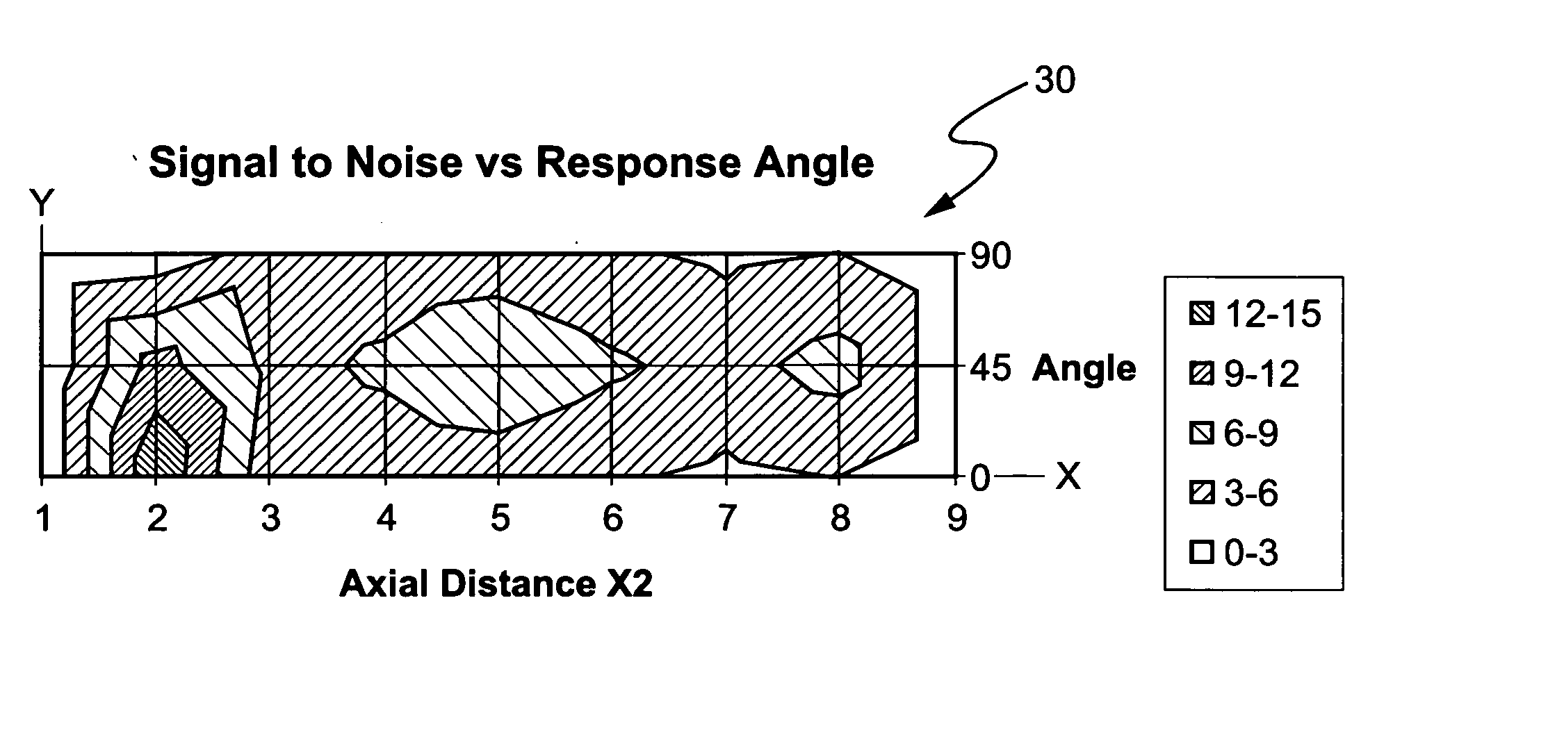
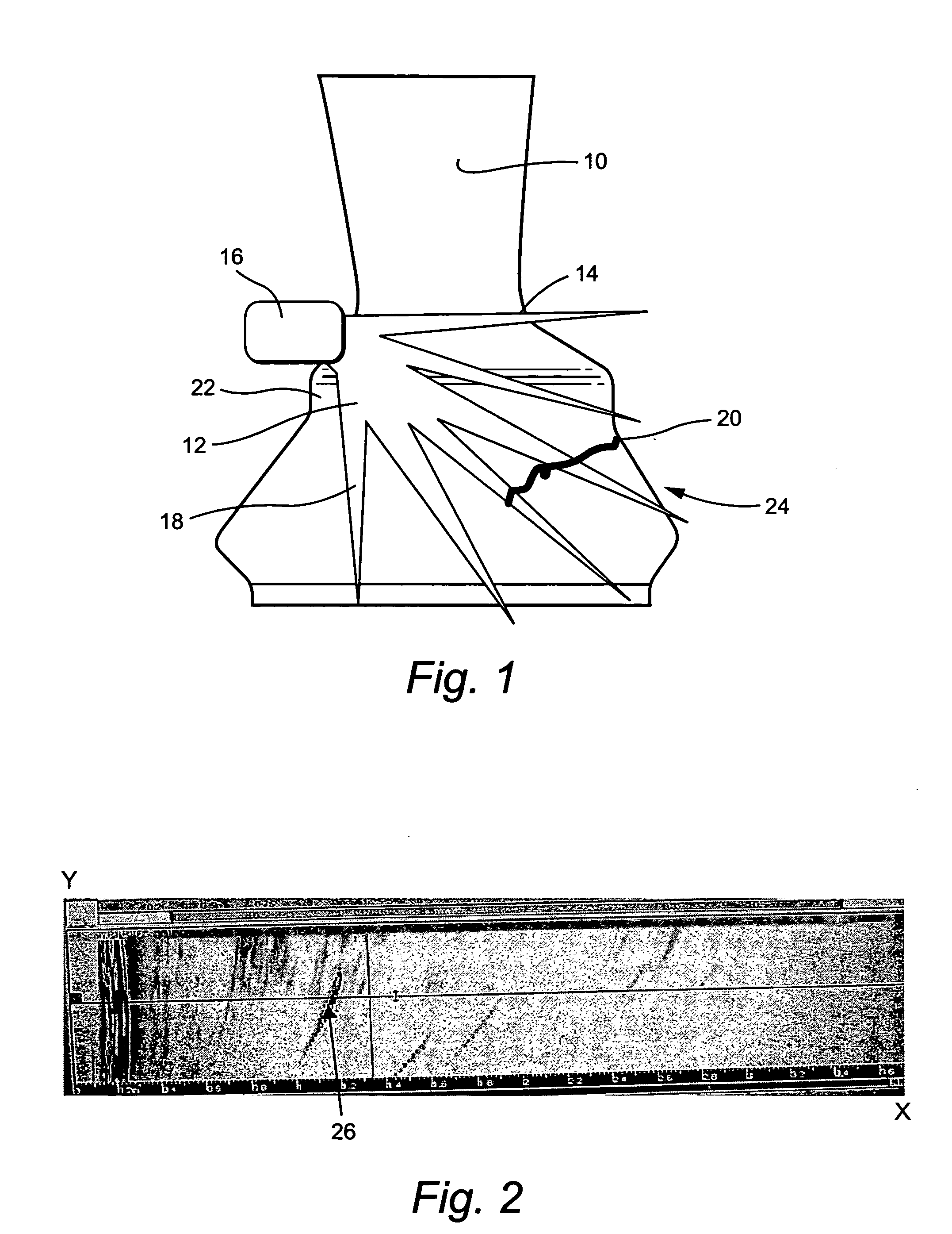
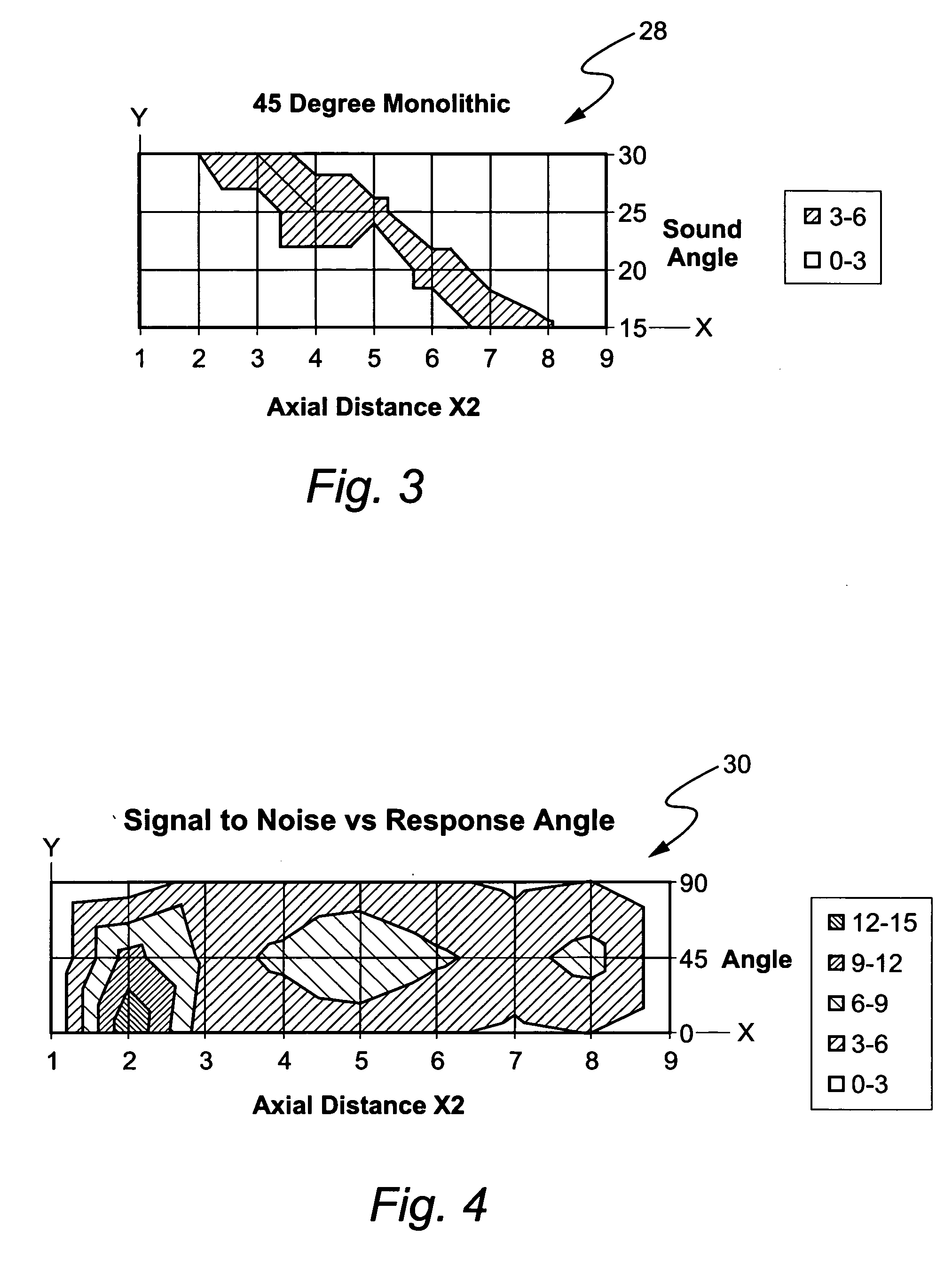
[0015] The present invention is directed to a method of nondestructively examining machine components, such as airfoils, for defects without removing the components from the machines of which they are a part. The method of the present invention uses well-known phased array ultrasound technology to nondestructively examine the components for defects, and is applicable to all types of components, in that it can be used to test any geometry where the surface of the component through which the ultrasonic sound beam enters changes in angle with respect to the part of the component to be examined for defects.

[0016] The method of the present invention is applicable to both longitudinal wave and shear wave techniques used to test components without removal of them from the machine containing them. The angle at which the ultrasonic beam enters a component to be examined is varied by the transducer probe emitting the beam. The phased array ultrasound allows an inspector to steer the ultrason...


PUM

PropertyMeasurementUnit
angle of incidenceaaaaaaaaaa
beam angleaaaaaaaaaa
scan angleaaaaaaaaaa

Abstract

A method is disclosed for nondestructively examining airfoils for defects without removing them from the turbine machines of which they are a part. The method uses phased array ultrasound technology, which can be used with all types of airfoils. The angle of entry of the ultrasonic beam is varied by using phased array ultrasound technology. The phased array ultrasound allows an inspector to steer the ultrasonic beam toward an area of interest within the airfoil. The phased array allows an inspector to monitor multiple angles at once. So long as the scan angle does not exceed a calibrated range, an inspector can monitor an area of interest, no matter what the sound beam entry surface angle is. The ultrasonic beam is steered or phased to inspect different orientations with one scan. The method uses a phased array transducer that is a linear array probe that is comprised of a series of transducers. Each of these transducers is programmed to trigger at predetermined time intervals and also receive at predetermined time intervals. The signals acquired by each transducer are then processed by a computer to give a composite view of a tested region so that a defect indication can be viewed.

Description

[0001] The present invention relates to a method for nondestructively examining for defects in machine components, such as airfoils, and in particular, to a method of nondestructively examining such components for defects using phased array ultrasound technology. BACKGROUND OF THE INVENTION [0002] With the development of modern, more complex aerodynamic power generation machines, there has been an increased amount of study into the inspection of machine components to develop methods of inspecting such components for defects in non-invasive ways. Some of the most critical components of the machines are in locations that allow limited access to them. Most studies to date have used visual, radiographic, liquid penetrant and eddy current non-destructive methods of inspection. To perform visual, liquid penetrant and eddy current tests, it is necessary to have access to all surfaces of the machine component being tested. For many machine components, this is not possible without at least s...

Claims


Application Information

Patent Timeline
Patent Type & Authority Applications(United States)
IPC IPC(8): G01N29/00G01B17/00G01N29/04G01N29/06G01N29/26G01N29/30
CPCG01N29/043G01N29/0609G01N29/262G01N2291/2693G01N2291/0421G01N2291/0422G01N2291/106G01N29/30
Inventor BERGMAN, ROBERT WILLIAM
Owner GENERAL ELECTRIC CO
Why Eureka
Try Eureka