Miter saw with angle adjustment

Inactive Publication Date: 2005-11-03
METABOWERKE
View PDF14 Cites 8 Cited by
  • Summary
  • Abstract
  • Description
  • Claims
  • Application Information

AI Technical Summary

Benefits of technology

[0018] If an angular position is to be continuously and reproducibly defined with the above described construction, the turntable can be moved first over the base such that the base and the turntable will be connected to one another via the locking means. By releasing the catch arm fixing device, the base can turn freely and as a result of the action of the locking means it follows the further turning of the turntable into the desired angular position. By tightening the catch arm fixing devi

Problems solved by technology

However, the continuously fixed angular position cannot be reproduc

Method used


Image

  • Miter saw with angle adjustment
  • Miter saw with angle adjustment
  • Miter saw with angle adjustment

Examples


Embodiment Construction

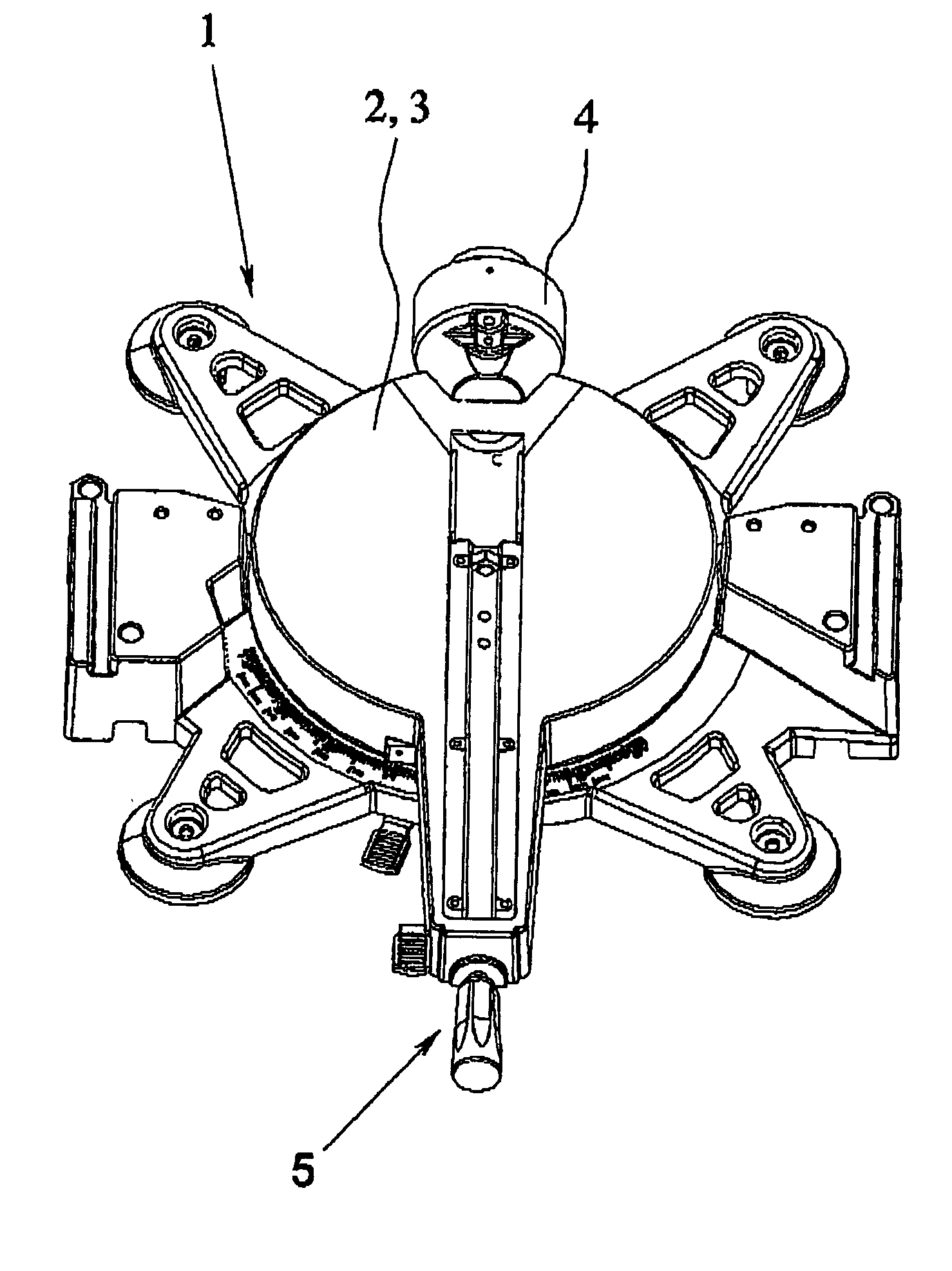
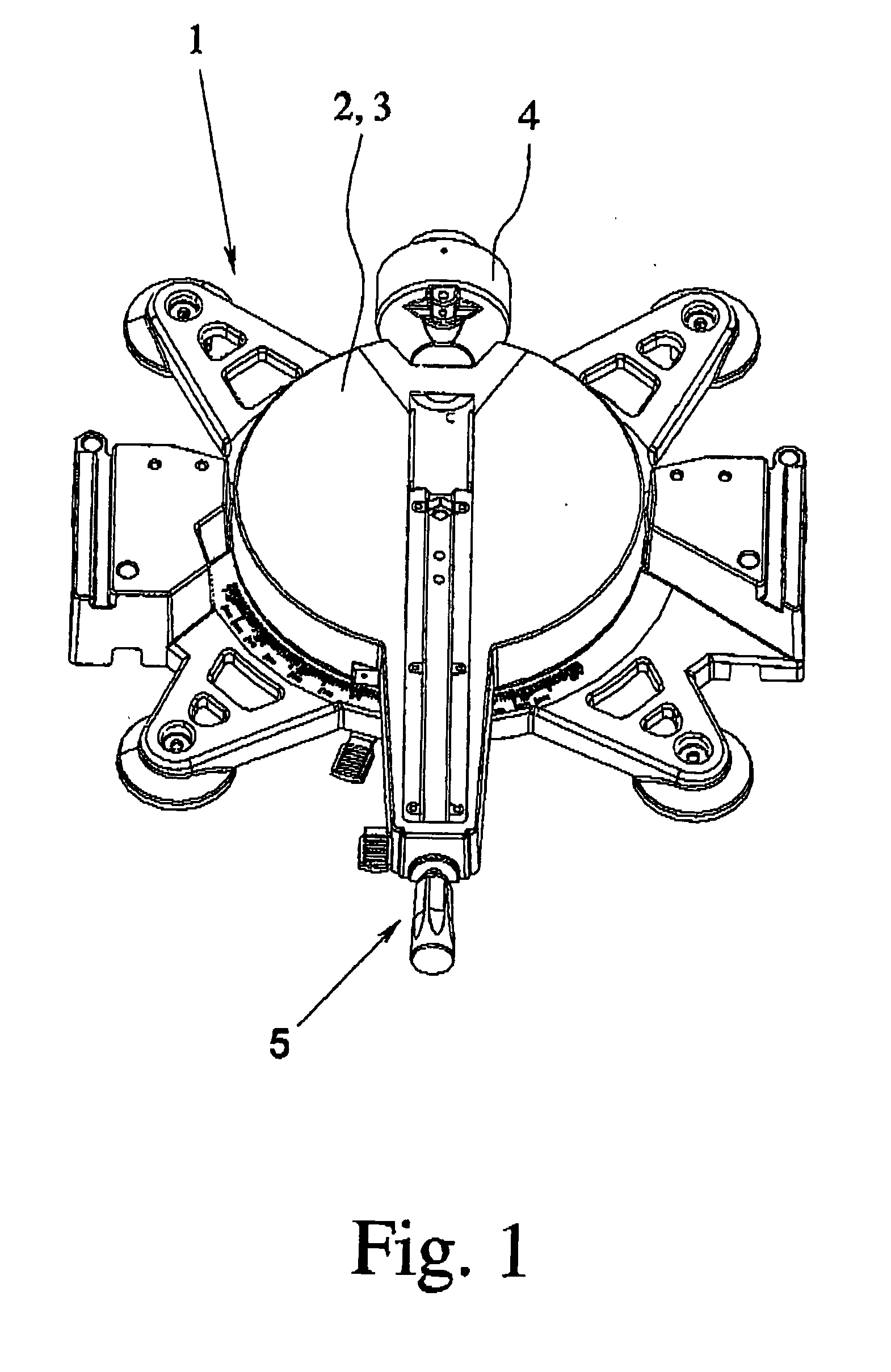
[0027] The miter saw in accordance with the invention is described below using one preferred embodiment of a combined crosscut saw and miter saw. The invention could also be equally well described using any other miter saw, such as, for example, using a circular table saw which allows miter cuts to be made, Therefore, quite in general, the sole prerequisite for implementation of the teaching is simply the function of a miter saw. More extensive functionalities which the miter saw can have, such as, for example, crosscutting, diagonal cutting and ripping function, can be available, but need not necessarily be so.

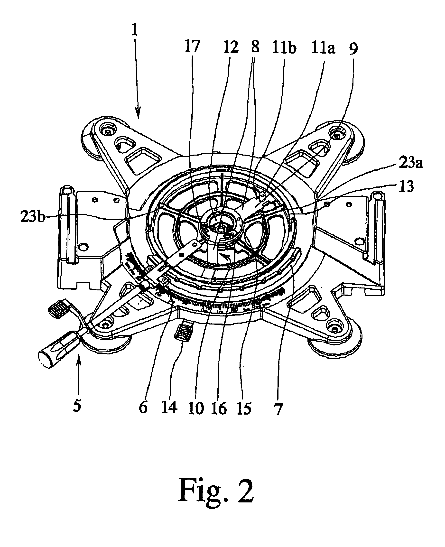
[0028] The miter saw shown in the figures is limited to only the important components which are necessary for explanation of the invention. Thus, the miter saw of the invention which is shown in FIG. 1 essentially comprises only a carrier 1 and a turntable 3 which forms a workpiece support surface 2. All other components which are functionally necessary for a combined crossc...


PUM

PropertyMeasurementUnit
Fractionaaaaaaaaaa
Forceaaaaaaaaaa
Angleaaaaaaaaaa

Abstract

A miter saw with angular adjustment has a carrier (1), a turntable (3) which is able to turn relative to the carrier (1) and which forms a workpiece support surface (2), and a turntable fixing device (8) for fixing the turntable (3) relative to the carrier (1) in certain reproducible angular positions. The miter saw turntable fixing device (8) enables adjustment of the angular position relative to the carrier in a manner which is continuous and mechanically reproducible.

Description

BACKGROUND OF THE INVENTION [0001] 1. Field of Invention [0002] This invention relates to a manual miter saw with angle adjustment arrangement having a carrier, a turntable which is mounted to the carrier so as to be able to turn relative to it and which forms a workpiece support surface, and a turntable fixing device for fixing the turntable relative to the carrier in certain reproducible angular positions within a working rant of possible angular positions. [0003] 2. Description of Related Art [0004] Miter saws of the type under consideration have been known for a long time in various embodiments, generally in conjunction with the use of circular saws. Miter saws with angle adjustment are used, for exanple, in the form of circular table saws (U.S Pat. No. 6,370,997) and also as combined crosscut saws and miter saws (U.S. Patent Application Publication Nos. 2002 / 0088327 A1 and 2004 / 0060412 A1). They are used to work all types of materials. One special application of these miter saw...

Claims


Application Information

Patent Timeline
IPC IPC(8): B23D47/02B23Q16/06B27B5/20B27B5/29B27G5/02
CPCB23D47/025B27G5/02B27B5/29B23Q16/065Y10T83/8773Y10T83/7705Y10T83/9457Y10T83/7697Y10T83/7726
Inventor BERGMANN, LAURENTIUS
Owner METABOWERKE
Why Eureka
Try Eureka