Combined pressure test and clean apparatus

a technology of pressure testing and cleaning apparatus, which is applied in the direction of fluid tightness measurement, cleaning using liquids, instruments, etc., can solve the problems of difficult cleaning of the interior passages of tubes and similar components with relatively small diameter interior passages, laborious and relatively expensive cleaning operations, etc., and achieves less setup time, capital expense, and wait time

Active Publication Date: 2005-11-03
THE BOEING CO
View PDF14 Cites 22 Cited by
  • Summary
  • Abstract
  • Description
  • Claims
  • Application Information

AI Technical Summary

Benefits of technology

[0009] The invention is an apparatus and method capable of cleaning the inside of hollow tube structures, welded assemblies, pump housings, and manifolds (collectively “tubular structures” or simply “parts”) and pressure testing the hollow tubular structures without the need to reconfigure, reposition, or relocate the tubular structures between the cleaning and testing phases. As such, the cleaning and testing phases may be streamlined so as to reduce overall production time.
[0014] The flow of cleaning fluid through the tubular structures cleans any oil, solvents, or debris from the inside of the parts. Pressurizing a fluid within the parts to above the rated service pressure of the parts provides assurance that the parts are mechanically sound and suitable for its intended purpose. The ability to both clean and pressure test the tube while the tube is affixed to a single apparatus allows both operations to be accomplished with less setup time, wait time, and capital expense relative to conventional techniques that utilize multiple machines to accomplish those functions.

Problems solved by technology

The cleaning of the interior of tubes and similar components with relatively small diameter interior passages and those which include throughout their length a number of bent or curved portions, is especially difficult, primarily as the result of the difficulty of inserting conventional tools or other cleaning apparatus into the part and moving it along the full tube or interior passage length.
As might be predicted, this resulted in a labor intensive and relatively expensive cleaning operation.
The processes of cleaning the various parts and pressure testing the various parts are both laborious and time consuming.
In fact, in the mass production of tubular structures, cleaning and pressure testing are often the bottleneck in production schedules due to the need to set up special equipment for each task and the need to wait for equipment availability before each new part or set of parts may be cleaned or tested.

Method used


Image

  • Combined pressure test and clean apparatus
  • Combined pressure test and clean apparatus
  • Combined pressure test and clean apparatus

Examples


Embodiment Construction

[0020] The present invention now will be described more fully hereinafter with reference to the accompanying drawings, in which preferred embodiments of the invention are shown. This invention may, however, be embodied in many different forms and should not be construed as limited to the embodiments set forth herein; rather, these embodiments are provided so that this disclosure will be thorough and complete, and will fully convey the scope of the invention to those skilled in the art. Like numbers refer to like elements throughout.

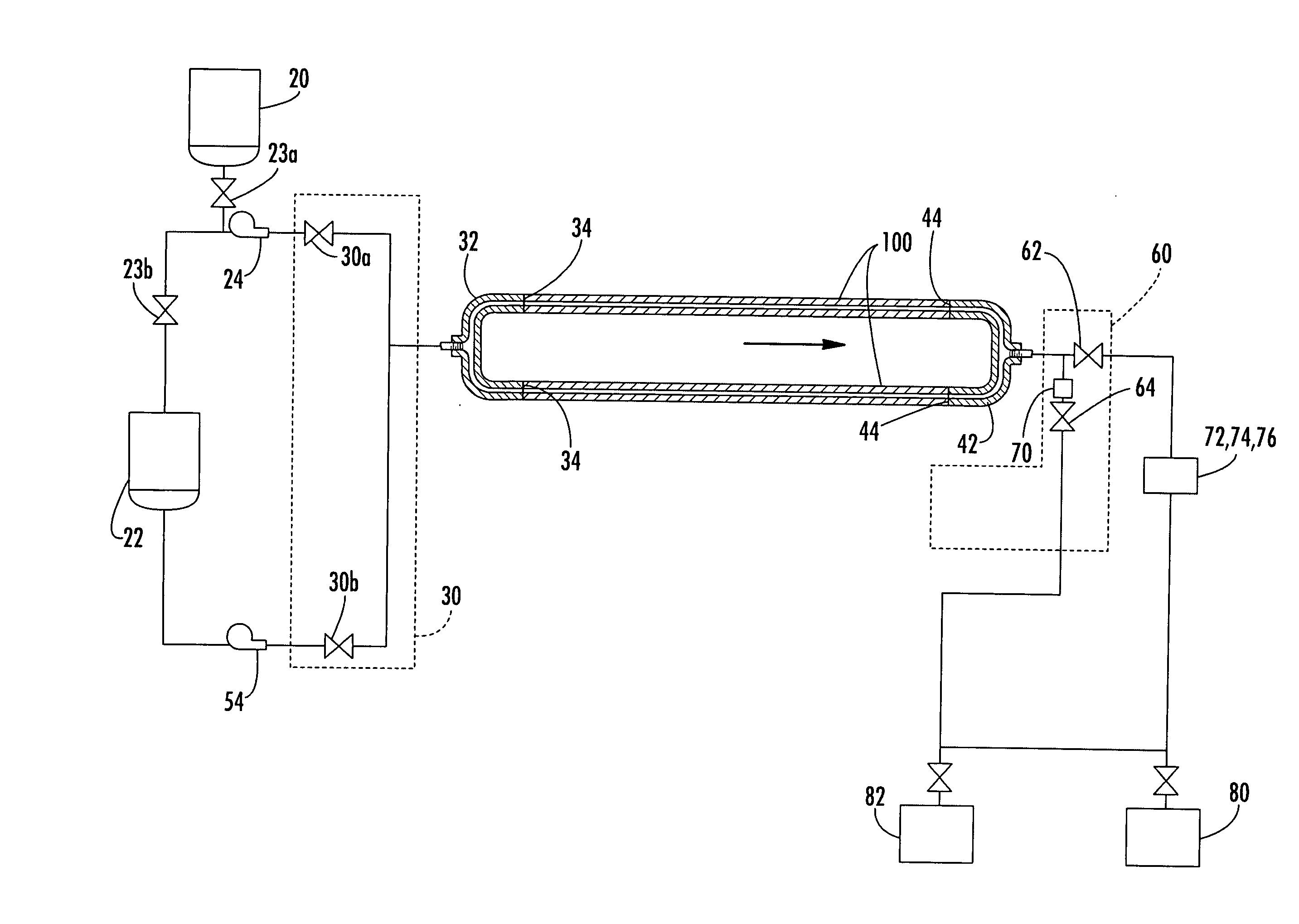
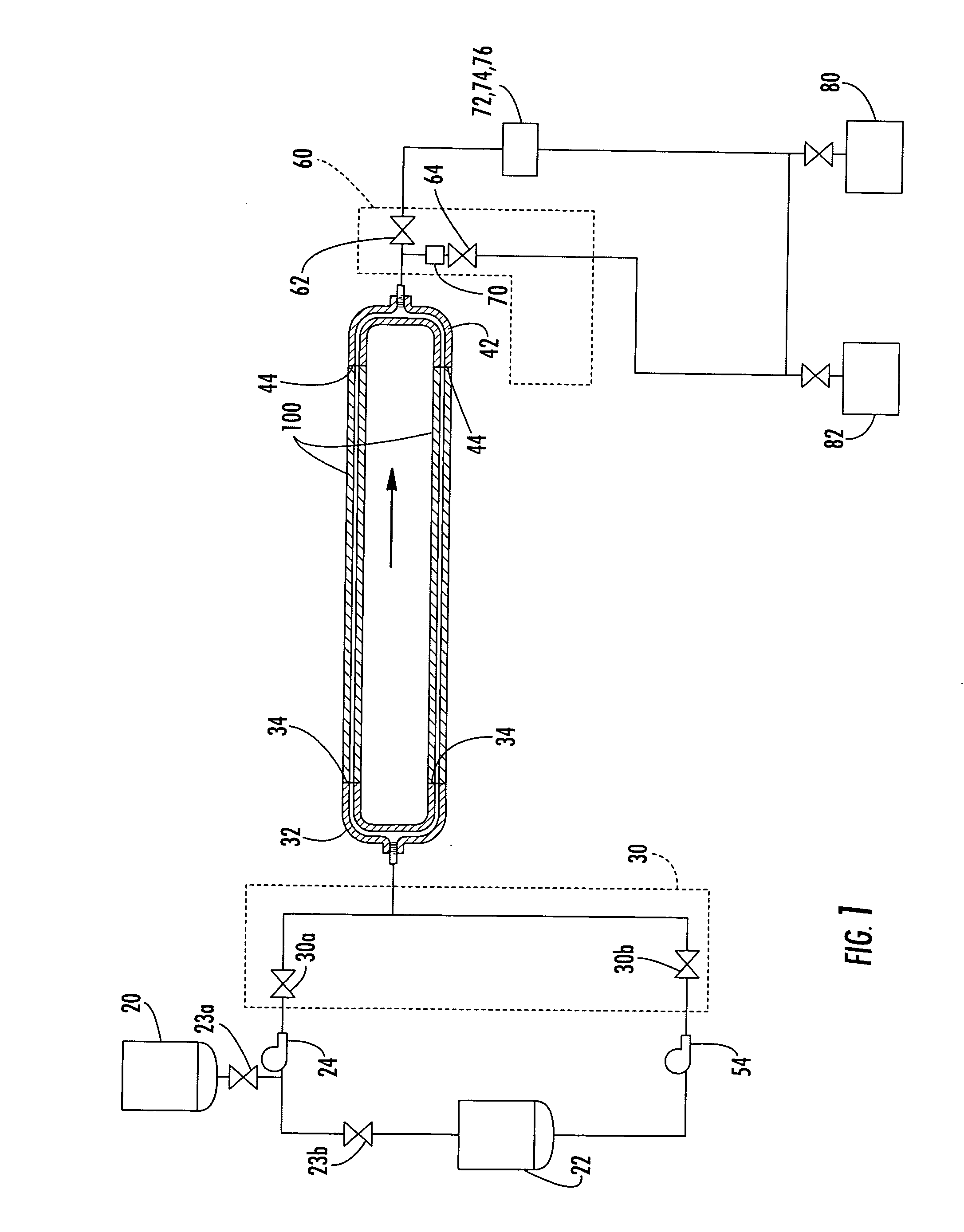
[0021] Referring to FIG. 1, according to one embodiment, the apparatus generally comprises a cleaning fluid supply pump 24 and a pressurization pump 54 that are alternatively placed in communication with a feed header 32 by operation of valves 30a, 30b of a feed valve network 30. Supply lines to the cleaning pump 24 are valved such that the cleaning pump may receive a feed of cleaning solution from a cleaning solution reservoir 20 or a rinsing solution r...


PUM

PropertyMeasurementUnit
pressuresaaaaaaaaaa
pressureaaaaaaaaaa
temperatureaaaaaaaaaa

Abstract

An apparatus for cleaning and pressure testing tube structures comprising a cleaning fluid supply pump and a pressurization pump alternately in fluid communication with a feed header having a feed header interface engageable to an end of at least one tube structure and a drain header having a drain header interface engageable to an opposing end of the at least one tube structure and an outlet valved so as to be selectively closed or opened depending on mode of operation of the apparatus. The apparatus cleans and pressure tests a tube by engaging a tube between the feed header interface and the drain header interface and maintaining said engagement while sequentially flowing a cleaning fluid through the inner diameter of the hollow tube, pressurizing a static fluid within the hollow tube, and releasing fluid from the tube.

Description

FIELD OF THE INVENTION [0001] The present invention relates to the manufacture of metal tubes, pump housings, manifolds, and welded assemblies, and, more particularly, to the cleaning and pressure testing of tubes, pump housings, manifolds, and welded assemblies, after fabrication. BACKGROUND OF THE INVENTION [0002] Tubular metallic structures, pump housings, manifolds, and welded assemblies (collectively referred to as “tubular structures”) are commonly manufactured for use in a variety of applications, such as industrial machinery, automobiles, and aerospace applications. Newly fabricated tubular structures undergo a number of cleaning and testing phases before they are passed on for actual use. For instance, when a tube is used as a transport medium for liquids or gases, the inside of the tube must be cleaned to ensure that the inside of the tube is free of contaminants and debris that might contaminate the fluid being transported. When a tubular structure is to be used for trans...

Claims


Application Information

Patent Timeline
Patent Type & Authority Applications(United States)
IPC IPC(8): B08B9/00B08B9/02G01M3/28G01N3/02G01N3/12
CPCB08B9/00B08B9/0321G01N2203/027G01M3/2846G01N3/12B08B9/0325
Inventor NEALON, JOSEPH M.
Owner THE BOEING CO
Why Eureka
Try Eureka