
Hose coupling device

a coupling device and hose technology, applied in the direction of hose connection, pipe connection arrangement, mechanical apparatus, etc., can solve the problems of limiting the use of hoses for certain applications, cumbersome implementation, ineffective approach to rapid coupling, etc., and achieve the effect of gripping

Inactive Publication Date: 2005-11-03
QL HLDG
View PDF6 Cites 23 Cited by
  • Summary
  • Abstract
  • Description
  • Claims
  • Application Information

AI Technical Summary

Benefits of technology

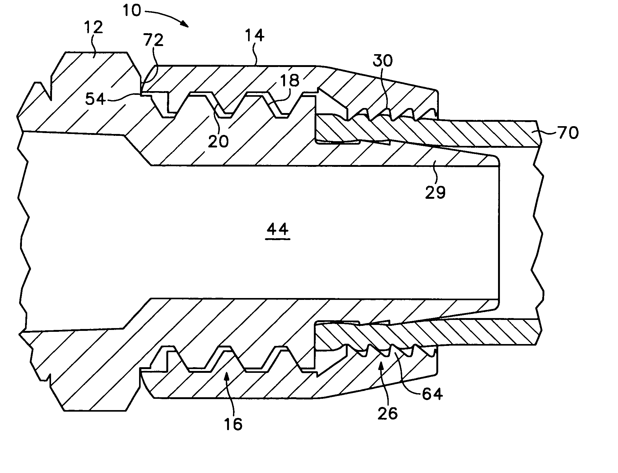
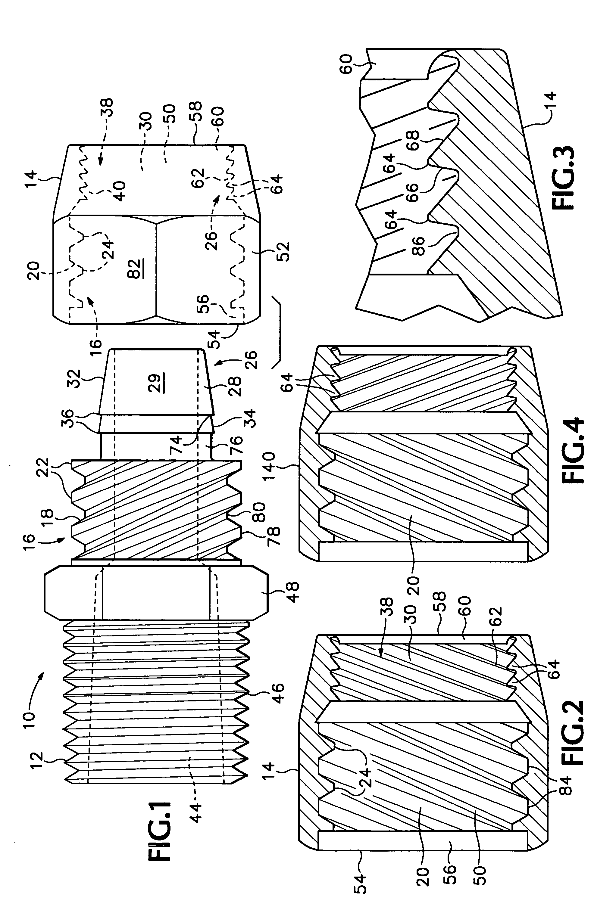
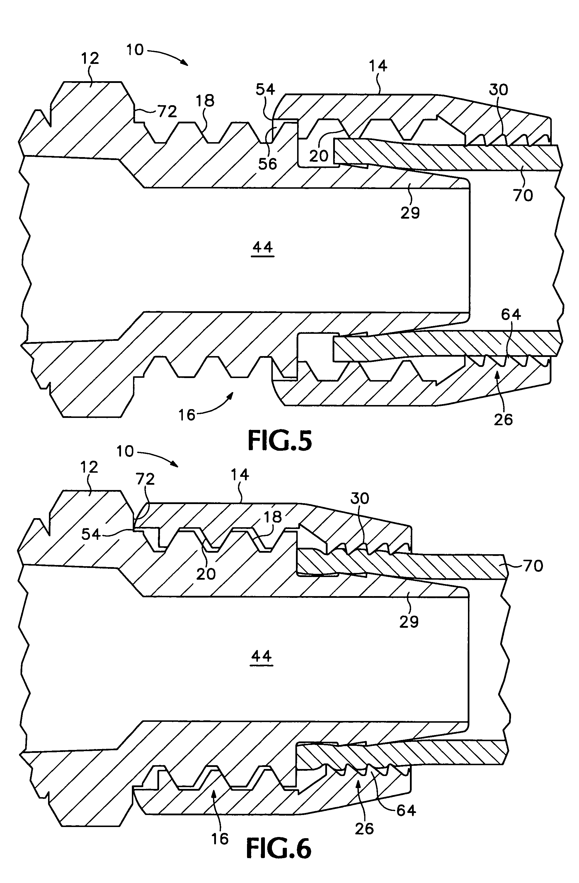
[0007] The invention provides hose coupling devices that securely connect an end of a hose to a fitting member to create a sealed conduit connection, using a retention mechanism operated by multi-threaded engagement of the fitting member with a collar member. The multi-threaded engagement also may operate a hose advancement mechanism. The advancement mechanism axially advances a hose during multi-threaded engagement so that the hose may be more effectively gripped by the retention mechanism.

Problems solved by technology

There are problems with these and other prior art couplers that may limit their use for certain applications.
In addition, many of these couplers use a single-threaded engagement mechanism that is cumbersome to implement.
These revolutions may require patience and may be an ineffective approach for rapidly coupling (and uncoupling) many hoses in a short time period.
Under time pressure, this alignment may not be achieved properly, resulting in ineffective coupling, and potentially, a damaged or ruined thread.
However, even if proper rotational engagement is achieved, many of these prior art couplers do not grip a hose effectively enough to handle a high side-load pressure without leaking.

Method used


Image

  • Hose coupling device
  • Hose coupling device
  • Hose coupling device

Examples


Embodiment Construction

[0018] The invention provides hose coupling devices that securely connect an end of a hose to a fitting member using a retention mechanism driven by multi-threaded engagement of the fitting member with a collar member. Multi-threaded engagement operates through plural threads on the fitting member and / or the collar member. These plural threads may allow each of the plural threads to advance at a greater pitch, thus producing a greater linear (axial) advancement of the collar member toward the fitting member per turn of the collar member. Accordingly, the fitting and collar members may operate / activate the retention mechanism to secure and sealingly retain a hose to the coupling device with less than a full turn of the collar member. In addition, the plural threads may allow the collar member to initiate engagement at a corresponding plural rotational positions around the perimeter of the fitting member, making engagement faster and easier still.

[0019] The retention mechanism may us...


PUM


Abstract

Hose coupling devices that securely connect an end of a hose to a fitting member using a retention mechanism operated by multi-threaded engagement of the fitting member with a collar member. The multi-threaded engagement also may operate a hose advancement mechanism. The advancement mechanism axially advances a hose during multi-threaded engagement so that the hose may be more effectively gripped by the retention mechanism.

Description

CROSS-REFERENCE TO RELATED APPLICATIONS [0001] This is a continuation application of U.S. patent application Ser. No. 10 / 683,140 filed Oct. 8, 2003 titled “Hose Coupling Device” which claims priority under 35 U.S.C. § 120 to PCT Application No. PCT / US02 / 11176 filed Apr. 9, 2002 titled “Hose Coupling Device,” which in turn claims priority under 35 U.S.C. § 119(e) to U.S. Provisional Patent Application Ser. No. 60 / 282,763 filed Apr. 9, 2001. Each of these applications is incorporated herein by reference in its entirety. [0002] This application incorporates herein by reference in its entirety for all purposes PCT Application No. PCT / US00 / 33404, filed Dec. 7, 2000.FIELD OF THE INVENTION [0003] The invention involves conduit coupling devices. In particular, the invention relates to conduit coupling devices that securely connect an end of a hose to a fluid conduit member to create a sealed conduit connection. BACKGROUND [0004] Hose coupling devices may be used for many purposes. For examp...

Claims


Application Information

Patent Timeline
IPC IPC(8): F16L33/22
CPCF16L33/223
Inventor EVANS, DANIEL C.LEUCK, N. JOHNLEWIS, DOUGLAS C.LYMAN, DANIEL J.
Owner QL HLDG
Learn More