Battery charging/discharging apparatus and battery charging/discharging method

a battery and discharging technology, applied in secondary cells, electrochemical generators, instruments, etc., can solve the problems of error between remaining capacity values and stored remaining capacity values, and achieve the effect of low cost and remaining battery capacity

Inactive Publication Date: 2005-11-03
SONY CORP
View PDF2 Cites 5 Cited by
  • Summary
  • Abstract
  • Description
  • Claims
  • Application Information

AI Technical Summary

Benefits of technology

[0028] Accordingly, based on the cell voltage which is detected, an appropriate remaining capacity value is read. The read remaining capacity value is then compared with a currently stored remaining capacity value to update the currently stored remaining capacity value based on the comparing result. This enables the remaining battery capacity to be determined at low cost with ease.

Problems solved by technology

Therefore, if the battery pack 1 is in standby mode for a long time, there is a problem in that the remaining capacity value stored in the memory 17a by the microcomputer 17 might be relatively greater than the actual remaining capacity value (actual capacity value).
There still exists such a problem that an error occurs between the remaining capacity value stored in the memory 17a and the actual capacity value.

Method used


Image

  • Battery charging/discharging apparatus and battery charging/discharging method
  • Battery charging/discharging apparatus and battery charging/discharging method
  • Battery charging/discharging apparatus and battery charging/discharging method

Examples


Embodiment Construction

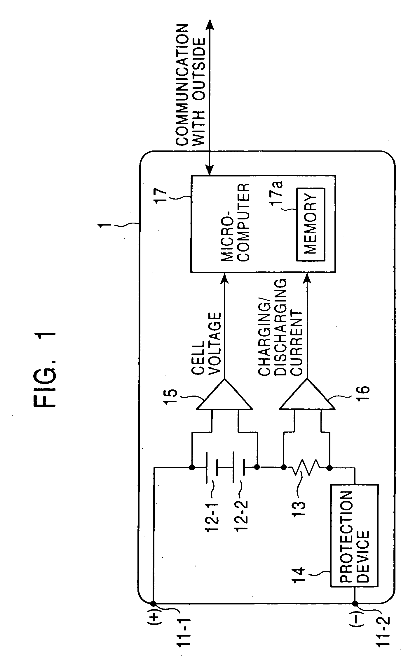
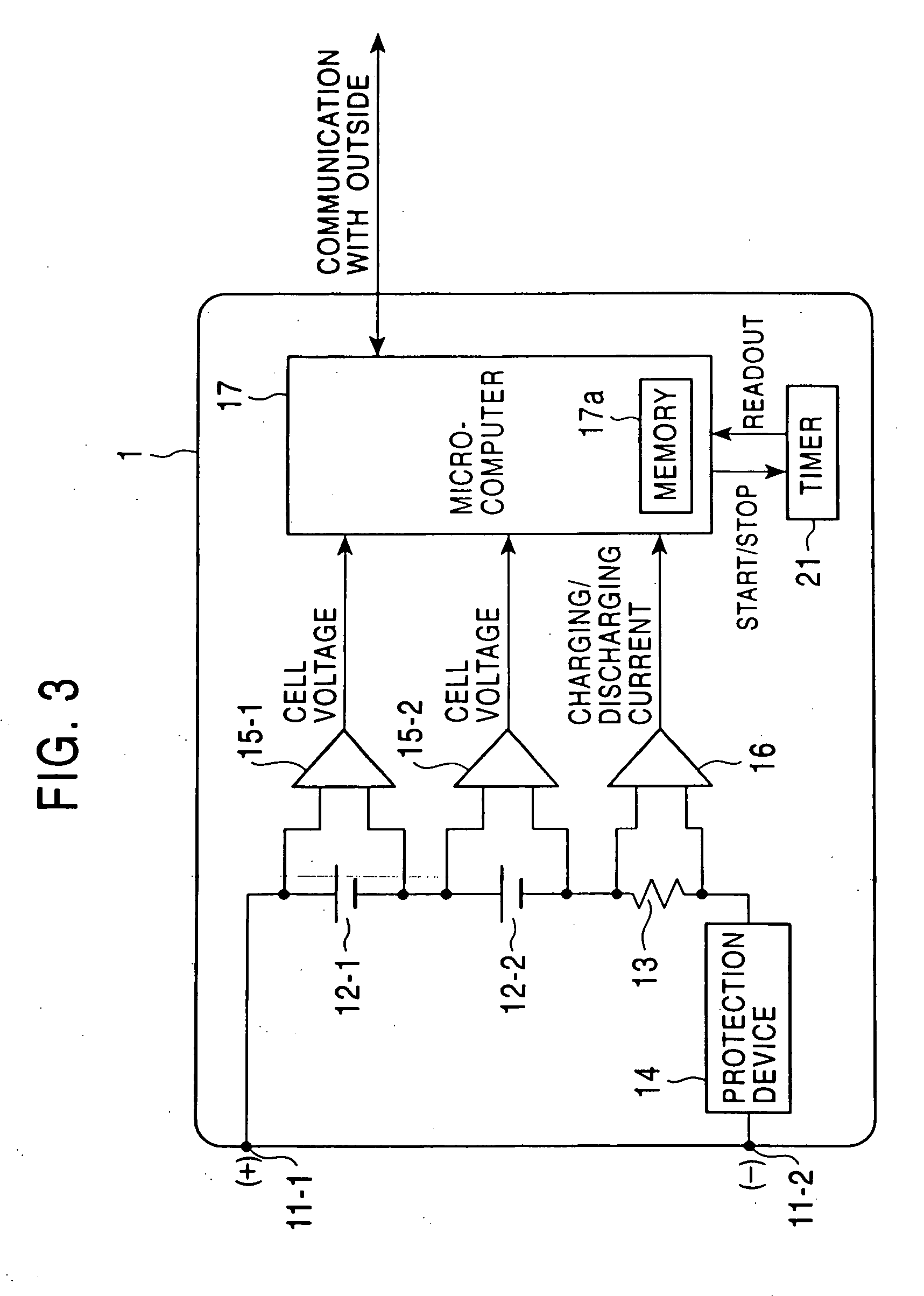
[0035]FIG. 3 is a block diagram of a battery pack 1 according to one embodiment of the present invention. The same reference numerals are assigned to the parts corresponding to those in the conventional one shown in FIG. 1, and a description thereof is thus omitted as appropriate.

[0036] Referring to FIG. 3, the battery pack 1 includes cell voltage detectors 15-1 and 15-2 coupled to the cells 12-1 and 12-2, respectively, to detect cell voltages with higher accuracy, and further includes a timer 21. Other parts are constructed in the same manner as those in the conventional one shown in FIG. 1.

[0037] The cell voltage detector 15-1 detects the cell voltage of the cell 12-1, and outputs the detection result to the microcomputer 17. The cell voltage detector 15-2 detects the cell voltage of the cell 12-2, and outputs the detection result to the microcomputer 17.

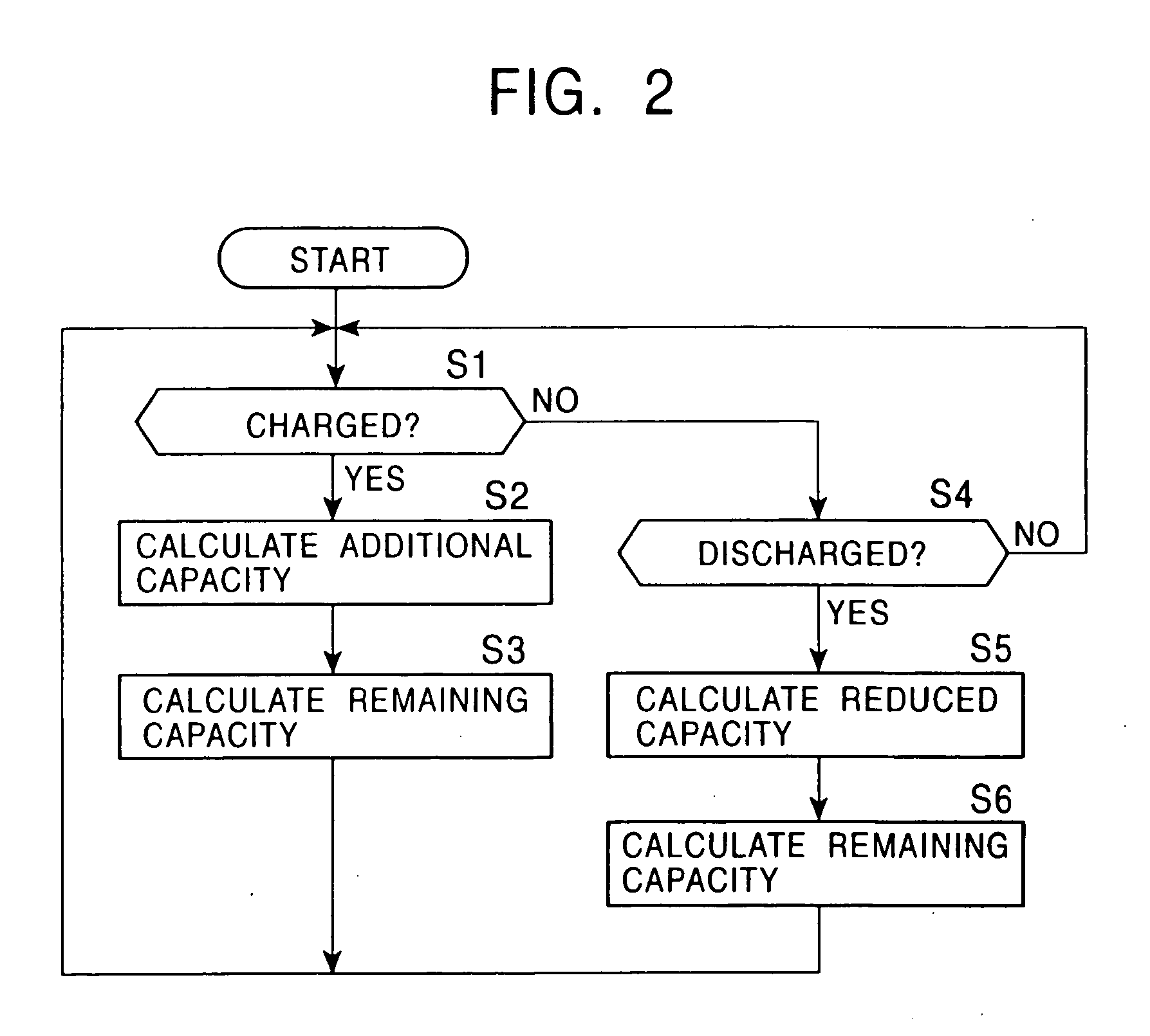
[0038] The microcomputer 17 calculates the remaining battery capacity value based on the cell voltages supplied from the cell...


PUM

PropertyMeasurementUnit
self-discharge currentaaaaaaaaaa
standby timeaaaaaaaaaa

Abstract

When a battery is in standby mode, a microcomputer switches to sleep mode if no charging/discharging current is supplied within a predetermined time, and controls a timer so as to start measuring the standby time of the battery. When a charging/discharging current is supplied, the microcomputer switches to wake-up mode, and controls the timer so as to stop measuring the standby time. Then, the microcomputer reads the measured standby time. Based on the read standby time, the microcomputer calculates the correction value to correct the currently stored remaining battery capacity value.

Description

BACKGROUND OF THE INVENTION 1. Field of the Invention [0001] The present invention generally relates to a charging / discharging apparatus, and particularly to a battery charging / discharging apparatus and a battery charging / discharging method in which the remaining capacity of a battery can be determined with high accuracy. [0002] 2. Description of the Related Art [0003]FIG. 1 is a block diagram showing an example structure of a conventional battery pack 1. [0004] The battery pack 1 includes cells 12-1 and 12-2 connected in series (hereinafter collectively referred to as “battery 12”, unless the cells 12-1 and 12-2 should be discriminated), which may comprise lithium ion batteries, for powering electronic devices. The positive electrode of the cell 12-1 is connected to a battery terminal 11-1 while the negative electrode of the cell 12-2 is connected to a battery terminal 11-2 via a resistor 13 provided for current detection and a protection device 14. When the battery pack 1 is attac...

Claims


Application Information

Patent Timeline
Patent Type & Authority Applications(United States)
IPC IPC(8): G01R31/36H01M10/44H02J7/00
CPCG01R31/3624H02J2007/005H02J7/0047G01R31/3655H01M10/48G01R31/3842H02J7/0048Y02E60/10H01M10/44H02J7/00712G01R31/3648
Inventor SUZUKI, MAMORUSATO, HIDEYUKI
Owner SONY CORP
Why Eureka
Try Eureka