Chemical reaction cartridge, method of producing chemical reaction cartridge, and mechanism for driving chemical reaction cartridge

a technology of chemical reaction and cartridge, which is applied in the direction of fluid speed measurement, chemical vapor deposition coating, combination devices, etc., can solve the problems of large personal error, high labor intensity, and the inability to move the solution easily, so as to reduce the friction between the cartridge and the pressing portion, the effect of smoothing the movement of the pressing portion

Active Publication Date: 2005-11-03
YOKOGAWA ELECTRIC CORP
View PDF7 Cites 112 Cited by
  • Summary
  • Abstract
  • Description
  • Claims
  • Application Information

AI Technical Summary

Benefits of technology

[0110] According to the mechanism for driving the chemical reaction cartridge described in the paragraphs (72) to (77), since the rollers are provided in the pressing portions or ends of the pressing portions are provided as curved surfaces, friction between the cartridge and the pressing portions can be reduced. When the ends of the pressing portions are provided

Problems solved by technology

In the background-art method using beakers, pipettes, etc., the operation is however troublesome and there is a problem in large personal error and much labor.
Moreover, in the case of a blood collec

Method used


Image

  • Chemical reaction cartridge, method of producing chemical reaction cartridge, and mechanism for driving chemical reaction cartridge
  • Chemical reaction cartridge, method of producing chemical reaction cartridge, and mechanism for driving chemical reaction cartridge
  • Chemical reaction cartridge, method of producing chemical reaction cartridge, and mechanism for driving chemical reaction cartridge

Examples


first embodiment

[0155]FIGS. 4A to 4C are explanatory views for explaining a method for producing a cartridge. The steps of the method for producing a cartridge will be described below with reference to FIGS. 4A to 4C.

[0156] (1) A mask 119 and a substrate 120 are prepared (FIG. 4A).

[0157] (2) The mask 119 is placed on the substrate 120 and plasma adhesive treatment is performed (FIG. 4B). As a result, the portion (hatched portion) of the substrate 120 except the mask 119 is plasma-treated so as to be adhesive (FIG. 4C).

[0158] (3) The mask 119 is removed and the substrate 120 is bonded to an elastic body not shown. Incidentally, a substance not activated by plasma may be used in place of the mask 119 so that the substance is applied on the non-adhesive portion 121 of the substrate 120 before the plasma adhesive treatment.

[0159] The plasma adhesive treatment concerned with PDMS is a known technique (e.g. see Plasma Materials Science Handbook, Ohmsha, Ltd., 1992) and the description thereof will be ...

second embodiment

[0160]FIGS. 5A and 5B are explanatory views for explaining a method for producing a chemical reaction cartridge. The steps of the method for producing a cartridge will be described below with reference to FIGS. 5A and 5B.

[0161] (1) A notch is provided around a non-adhesive portion 125 of a substrate 122 and an adhesive agent 124 is applied so that the notch is filled with the adhesive agent 124. The notch may be formed in such a manner that the portion except the non-adhesive portion is cut off as shown in FIG. 5A or in such a manner that a groove is formed around the non-adhesive portion as shown in FIG. 5B.

[0162] (2) The substrate 122 is bonded to an elastic body 123.

[0163] Incidentally, the notch in the substrate 122 is provided for preventing the adhesive agent 124 from flowing into the non-adhesive portion. If a non-adhesive substance is applied on the non-adhesive portion 125 before bonding, it is unnecessary to provide the notch in the substrate 122.

third embodiment

[0164]FIG. 6 is an explanatory view for explaining a method for producing a chemical reaction cartridge. The steps of the method for producing a cartridge will be described with reference to FIG. 6.

[0165] (1) An implantable material 128 having a non-adhesive surface is placed on a non-adhesive portion 129 of an elastic body 127.

[0166] (2) A raw material of a substrate 126 is poured onto the elastic body 127 from above and hardened (e.g. casting molding).

[0167] As a result, the elastic body 127 and the substrate 126 are bonded to each other except the implantable material 128. Incidentally, for example, the implantable material 128 can be made from PDMS.

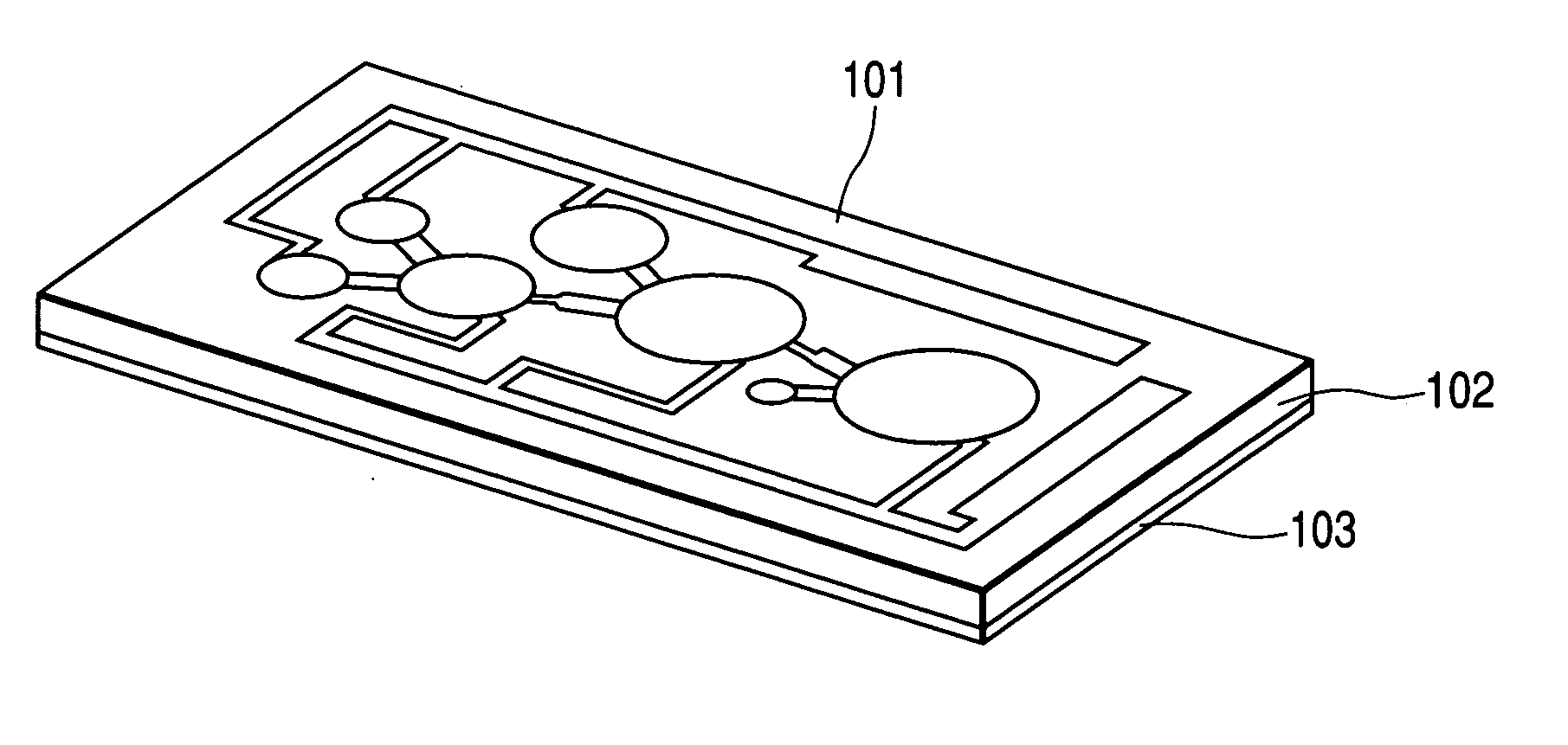
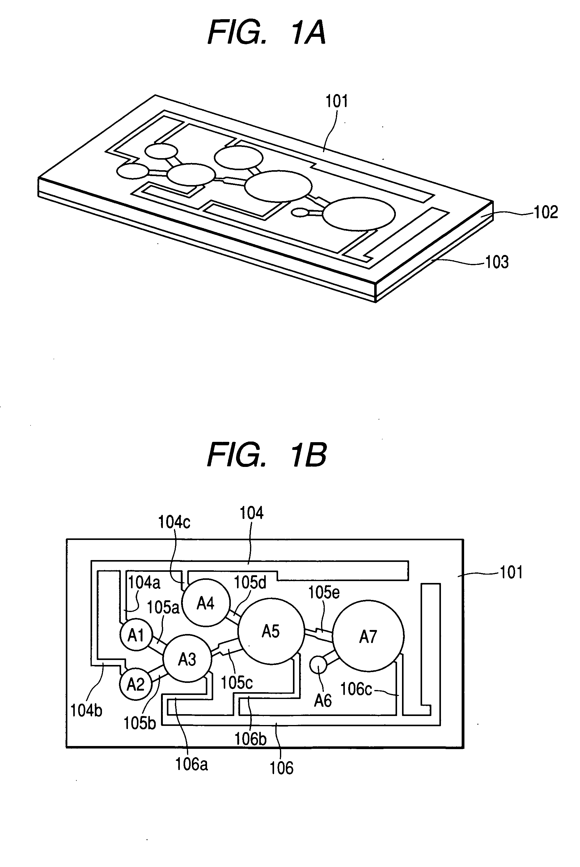
[0168] The configuration of a chemical reaction cartridge and a driving mechanism for transporting a solution in the cartridge will be described below.

[0169]FIGS. 7A to 7C are explanatory views showing a first embodiment concerned with the chemical reaction cartridge and the driving mechanism.

[0170] In FIG. 7A, a roller 130a is p...


PUM

PropertyMeasurementUnit
Fractionaaaaaaaaaa
Angleaaaaaaaaaa
Angleaaaaaaaaaa

Abstract

A chemical reaction cartridge includes a vessel having at least one part made of an elastic body, in which a plurality of chambers formed in the vessel so as to be connected or arranged connectably through a flow path, and an external force is applied to the elastic body from an outside of the vessel to move a fluid substance in the flow path or the chambers or in both the flow path and the chambers so as to perform a chemical reaction. At least a chamber into which the fluid substance is flowed has an air-release path which releases air from the chamber.

Description

CROSS-REFERENCE TO RELATED APPLICATIONS [0001] This application is based upon and claims the benefit of priority from the prior Japanese Patent Applications No. 2004-133060 filed on Apr. 28, 2004 and No. 2004-204085 filed on Jul. 12, 2004, and the entire contents of which are incorporated herein by reference. BACKGROUND OF THE INVENTION [0002] 1. Field of the Invention [0003] The present invention relates to a chemical reaction cartridge, a method for producing a chemical reaction cartridge and a mechanism for driving a chemical reaction cartridge. Particularly it relates to improvement in liquid supply structure concerned with synthesis, dissolution, detection, separation, etc. of a solution. [0004] 2. Description of the Related Art [0005] Test tubes, beakers, pipettes, etc. are heretofore generally used for synthesis, dissolution, detection, separation, etc. of a solution. For example, substance A and substance B are taken in test tubes, beakers, or the like, in advance. The subst...

Claims


Application Information

Patent Timeline
IPC IPC(8): B01D50/00B01F13/00B01F15/02B01J19/00B01L3/00B01L99/00B81B1/00B81C1/00G01N33/48G01N35/08
CPCB01F13/0059B01L2400/0655B01F15/025B01J19/0093B01J2219/00783B01J2219/00804B01J2219/00833B01L3/502707B01L3/502723B01L3/50273B01L2200/0621B01L2200/0684B01L2200/10B01L2300/0681B01L2300/0816B01L2300/0861B01L2300/0864B01L2300/0867B01L2300/087B01L2400/0481B01F15/0201B01F33/30B01F35/71B01F35/7177
Inventor TANAAMI, TAKEOKATAKURA, HISAOMITSUMORI, YUJIHIRAMATSU, HITOSHI
Owner YOKOGAWA ELECTRIC CORP
Why Eureka
Try Eureka