Wireless access point (WAP)

a wireless access point and access point technology, applied in the field of wireless access points (wap), can solve the problems of limiting their placement relative to furniture and other obstructions, suffering from several limitations, and creating an unappealing estheti

Inactive Publication Date: 2005-11-03
ONQ TECH
View PDF9 Cites 83 Cited by
  • Summary
  • Abstract
  • Description
  • Claims
  • Application Information

AI Technical Summary

Problems solved by technology

While these WAP's provide mobility, especially for laptop computers, and accessibility to alternate locations without running hardwires, they suffer from several limitations.
Existing Warp's need to rest on a flat surface, taking-up space on a shelf or piece of fur

Method used


Image

  • Wireless access point (WAP)
  • Wireless access point (WAP)
  • Wireless access point (WAP)

Examples


Embodiment Construction

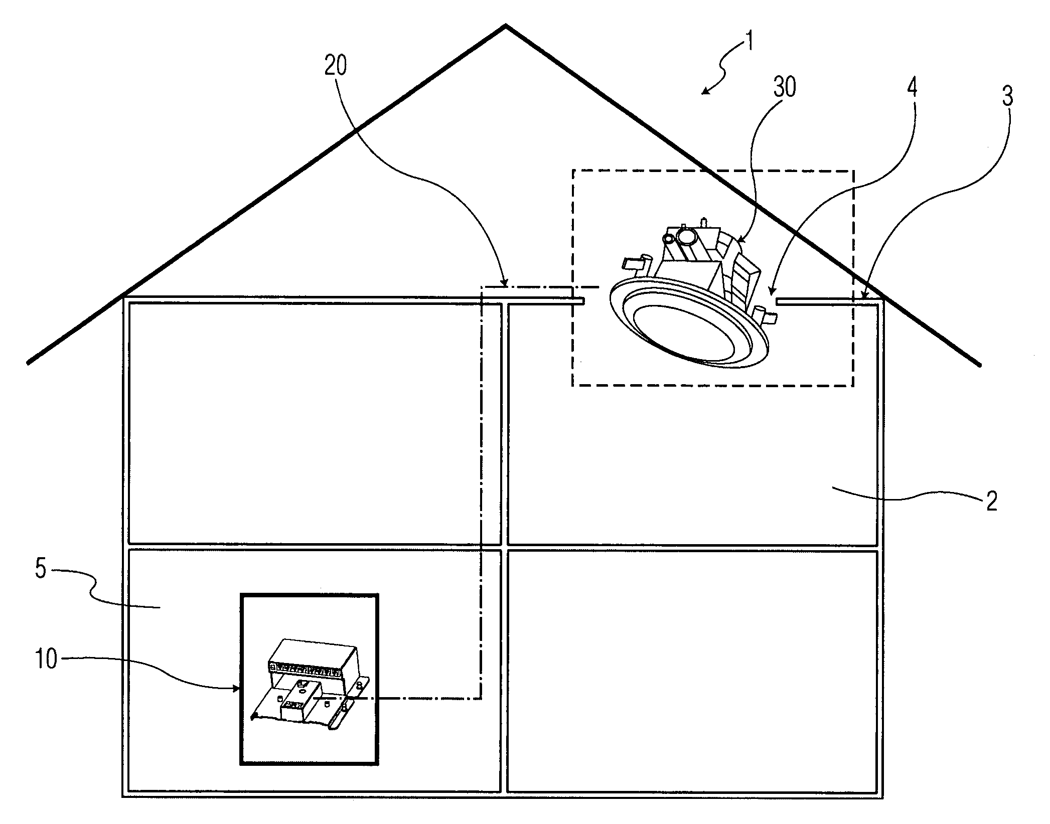
[0012] The invention provides a wireless access point assembly, a modular wireless access point system, and a wireless networking system to form a wireless zone as part of a home communication network. As shown in FIG. 1, a home 1 is provided with a communication network, which includes a service center 10, and at least one cable run 20, extending from the service center 10 to a location remote from the service center 10. According to an exemplary embodiment of the invention, a wireless access point (WAP) assembly 30 is connected to the cable run 20 to form a wireless zone 2. The WAP assembly 30 is mounted in an opening 4 in a ceiling 3 of the home 1, essentially centrally located in the wireless zone 2. By locating the WAP 30 in the ceiling 3, it can be essentially transparent to the homeowner, allowing a more esthetically pleasing room layout than if an existing WAP were simple placed on a table.

[0013] The communications network, may be, for example, an OnQ Home Network System, a...


PUM


Abstract

A wireless access point system provides a wireless access zone as part of a home communication network. A power injector is provided proximate a router/switch for a home communication network to inject power into a cable run extending from the router/switch to a remote location for the wireless access zone. A wireless access point assembly is mounted in a ceiling or wall to provide the wireless access zone. The wireless access point assembly includes an active access point and a power extractor connectable to the cable run to separately provide power and a communication link from the cable run to the active access point.

Description

FIELD OF THE INVENTION [0001] The invention relates to a wireless access point (WAP) and more particularly to an apparatus and method for integrating a wireless access point into a home network. BACKGROUND OF THE INVENTION [0002] Wireless access points (WAP's), such as the model WA840G, available from Motorola, Inc. of Schaumburg, Ill., are known for providing one or more computers with access to a computer network and / or to the Internet, using radio frequency (RF) transmissions. While these WAP's provide mobility, especially for laptop computers, and accessibility to alternate locations without running hardwires, they suffer from several limitations. Existing Warp's need to rest on a flat surface, taking-up space on a shelf or piece of furniture, and creating an unappealing esthetic. WAP's require a line of sight for RF transmission, limiting their placement relative to furniture and other obstructions. Also, WAP's require power, limiting their placement to locations where electric...

Claims


Application Information

Patent Timeline
IPC IPC(8): H04L12/28H04W52/00H04W88/08
CPCH04W52/0206H04W88/08Y02D30/70
Inventor HALL, LAWRENCE ALTON
Owner ONQ TECH
Why Eureka
Try Eureka