Differential carrier assembly

a carrier and differential technology, applied in the direction of differential gearings, belts/chains/gearrings, gear details, etc., can solve the problems of time-consuming, complicated, and therefore expensive correct assembly of differential carriers, and achieve the effects of less adjustment, easy machine assembly, and reduced labor

Inactive Publication Date: 2005-11-03
MERITOR HEAVY VEHICLE SYST CAMERI
View PDF14 Cites 52 Cited by
  • Summary
  • Abstract
  • Description
  • Claims
  • Application Information

AI Technical Summary

Benefits of technology

[0006] An object of the present invention is to provide a differential carrier assembly that is easier to assemble. Another object of the present invention is to provide a differential carrier assembly that requires less adjustment to correctly assemble. Another object of the present invention is to provide a differential carrier assembly that is easier to machine.

Problems solved by technology

For these reasons, the correct assembly of a differential carrier is time consuming, complicated, and therefore expensive.

Method used


Image

  • Differential carrier assembly
  • Differential carrier assembly
  • Differential carrier assembly

Examples


Embodiment Construction

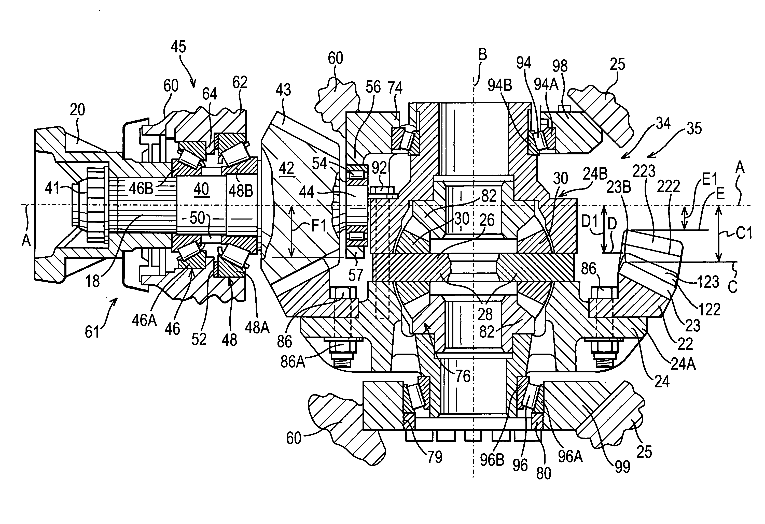
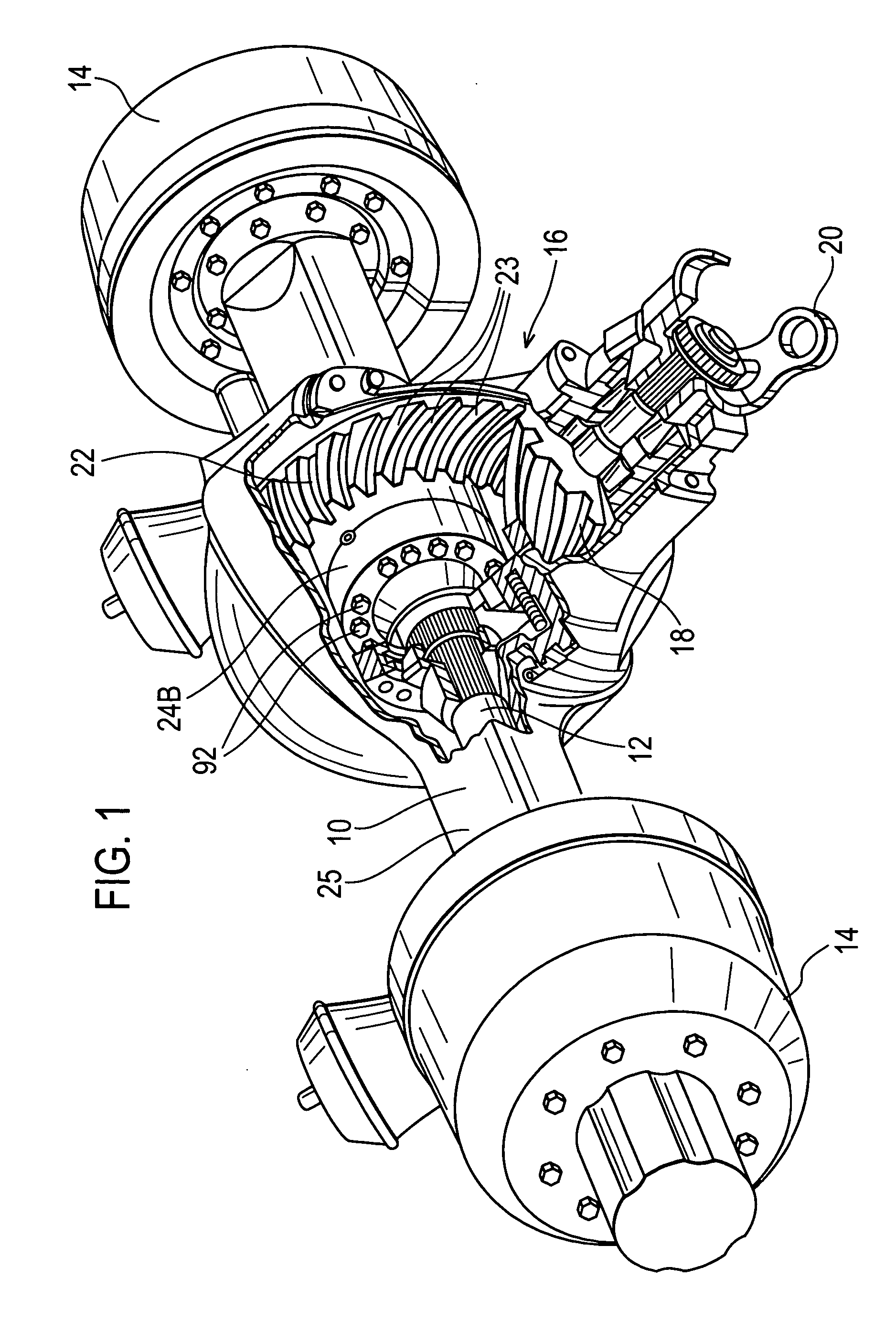
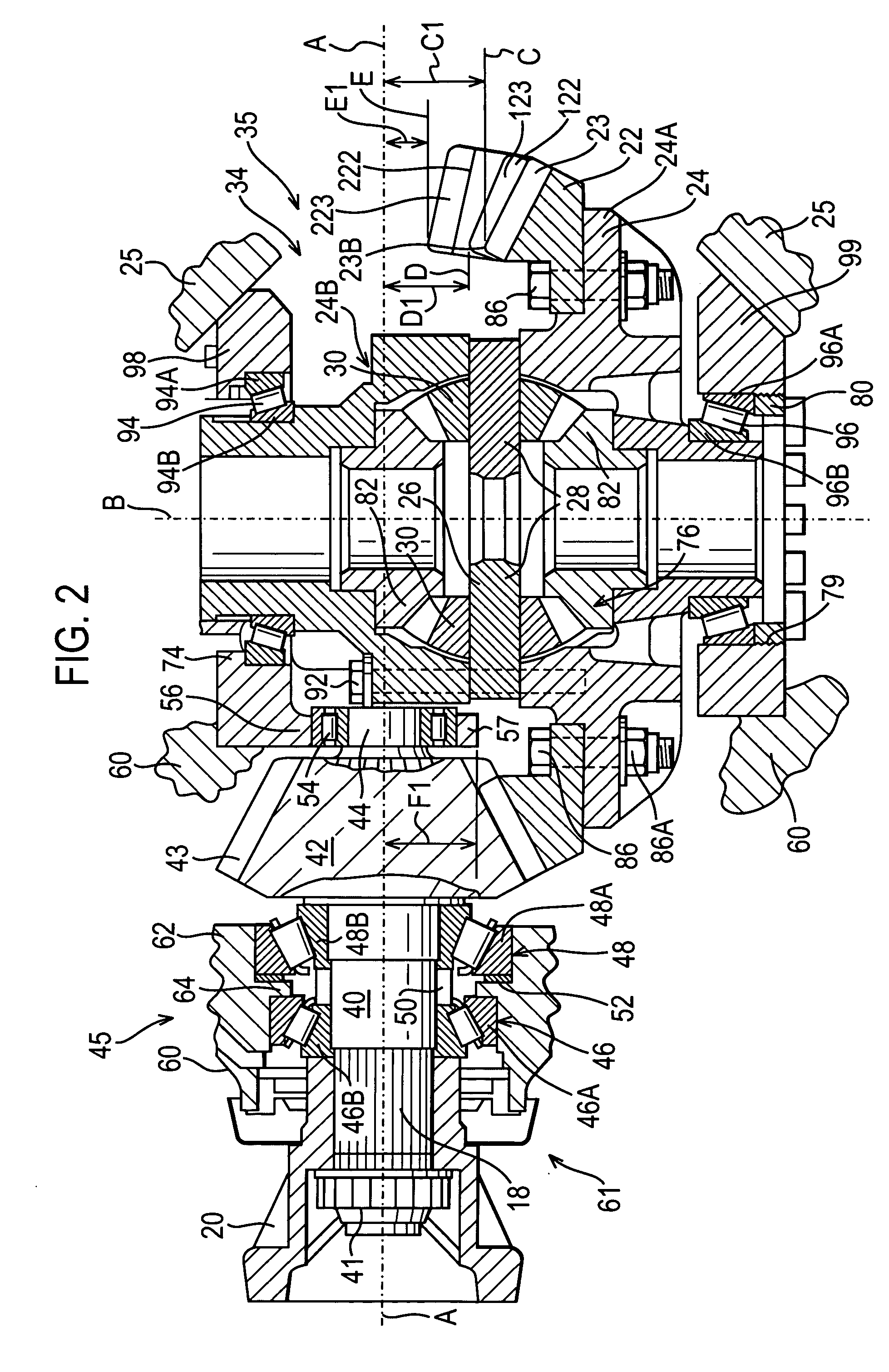
[0016]FIG. 1 shows a drive axle 10 which includes a pair of axle shafts 12 (only one of which is shown) for driving wheels (not shown) secured to wheel hubs 14. When the vehicle is driven along a straight path, the wheel hubs 14 turn at approximately the same speed, and the drive torque will be equally split between both wheels. When the vehicle turns, the outer wheel has to travel over a greater distance than the inner wheel. A differential assembly 16 allows the inner wheel to turn more slowly than the outer wheel as the vehicle turns.

[0017] Power is transmitted from an engine and transmission (not shown) to the drive axle 10 via a longitudinally extending drive shaft (not shown). The drive shaft is coupled to an input pinion 18 via a yoke assembly 20. The input pinion 18 is in constant mesh with a differential ring gear 22. As shown in FIG. 2, the differential ring gear 22 is bolted (via bolts 86 and nuts 86A) to a differential casing 24 that turns with the differential ring gea...


PUM


Abstract

A differential carrier assembly includes a differential carrier and a differential casing having a ring gear that is supported on right and left differential bearings for rotation about a differential axis. The right and left differential bearings are each supported in respective right and left bearing housings. A pinion having a pinion gear meshes with the ring gear and includes a spigot positioned on a differential axis side of the pinion gear. The spigot is supported in a spigot bearing, and the spigot bearing is supported in a spigot bearing housing. One of the right or left bearing housings and the spigot bearing housing are formed on a common component which is separate from and securable to the differential carrier.

Description

REFERENCE TO RELATED APPLICATIONS [0001] This application claims priority to United Kingdom Patent Application GB 0409418.1 filed on Apr. 28, 2004. BACKGROUND OF THE INVENTION [0002] The present invention relates to differential carrier assemblies. [0003] Known differential carrier assemblies include several components, the primary components being a differential carrier, an input pinion, a ring gear and a differential casing. Various components are mounted on bearings, and it is important to ensure the correct pre-load on certain bearings during assembly. It is also important to ensure the correct back lash between the ring gear and the input pinion. Thus, it is necessary to ensure that the input pinion is positioned longitudinally (relative to the pinion axis) correctly relative to the ring gear. It is also important to ensure that the ring gear is correctly positioned laterally (relative to the input pinion axis). For these reasons, the correct assembly of a differential carrier ...

Claims


Application Information

Patent Timeline
Patent Type & Authority Applications(United States)
IPC IPC(8): F16H48/06F16H48/08F16H48/38F16H48/40F16H48/42F16H57/021F16H57/037
CPCF16H48/08F16H48/40F16H48/42F16H57/021F16H2048/426F16H2048/382F16H2048/385F16H2048/405F16H2048/423F16H57/037
Inventor PONTANARI, MARCOGIANONE, ROBERTOMAGNAGO, CLEMENTE
Owner MERITOR HEAVY VEHICLE SYST CAMERI
Why Eureka
Try Eureka