Tool

Inactive Publication Date: 2005-11-03
FINSBURY DEV
View PDF9 Cites 232 Cited by
  • Summary
  • Abstract
  • Description
  • Claims
  • Application Information

AI Technical Summary

Benefits of technology

[0034] The cannulated rod will preferably have teeth located at the distal end thereof which in use can be driven into the surface of the femoral head. When driven into the head, these teeth help to clamp the alignment tool in position

Problems solved by technology

Diseases such as rheumatoid- and osteo-arthritis can cause erosion of the cartilage lining of the acetabulum so that the ball of the femur and the hip bone rub together causing pain and further erosion.
Bone erosion may cause the bones themselves to attempt to compensate for the erosion which may result in the bone being r

Method used


Image

  • Tool
  • Tool
  • Tool

Examples


first embodiment

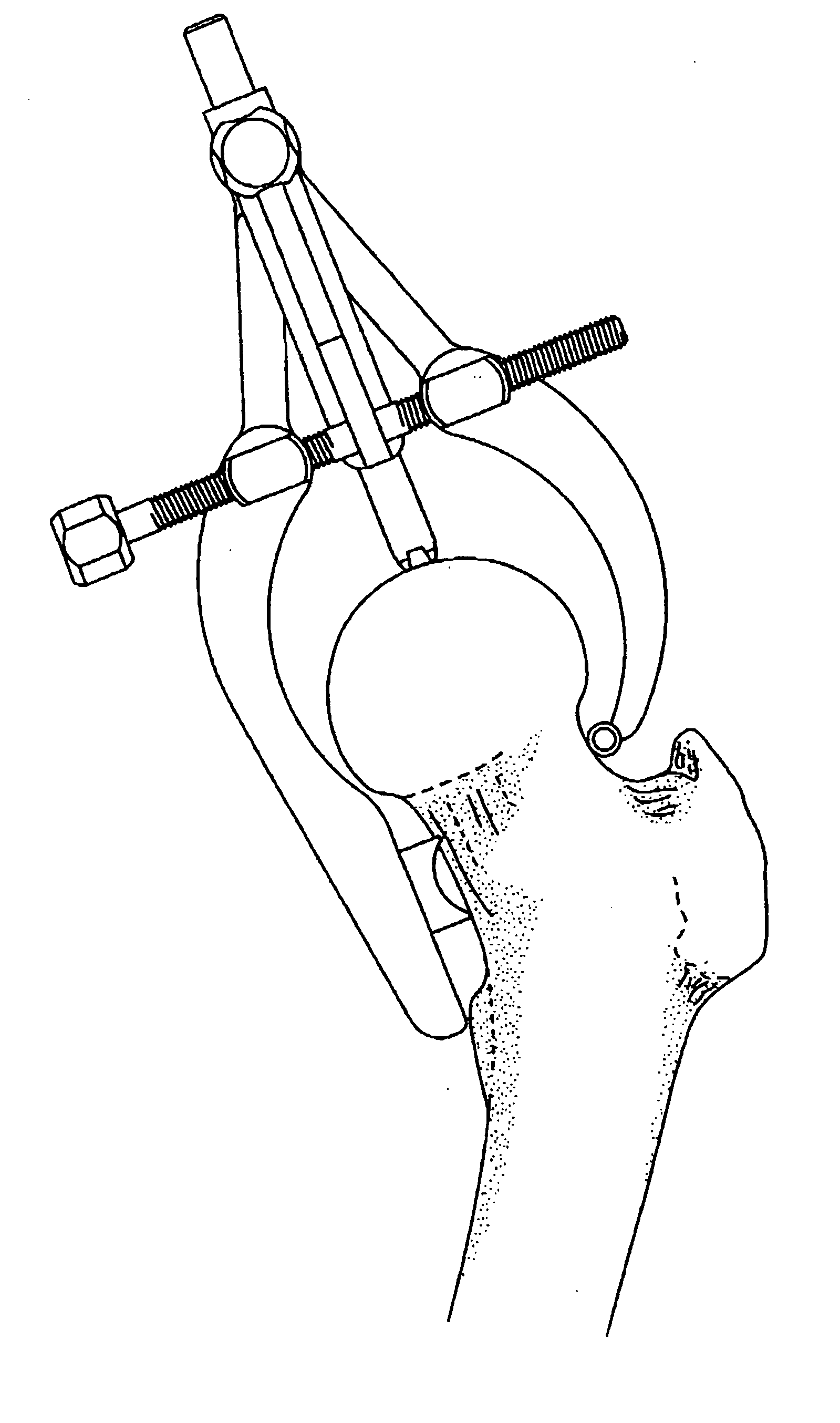
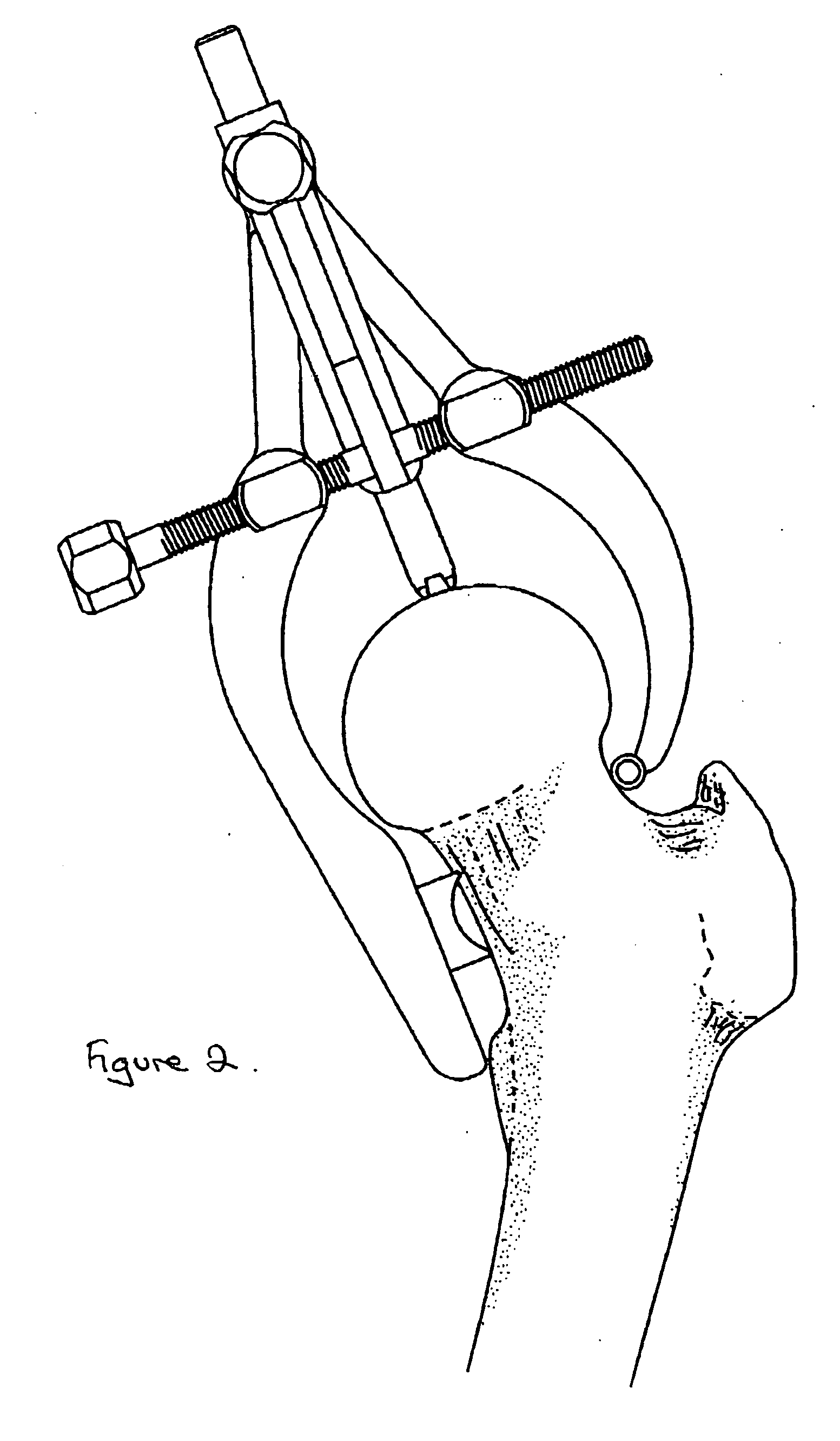
[0079] The tool of the present invention in the clamped position on the neck of a femur is illustrated schematically in FIG. 2.

second embodiment

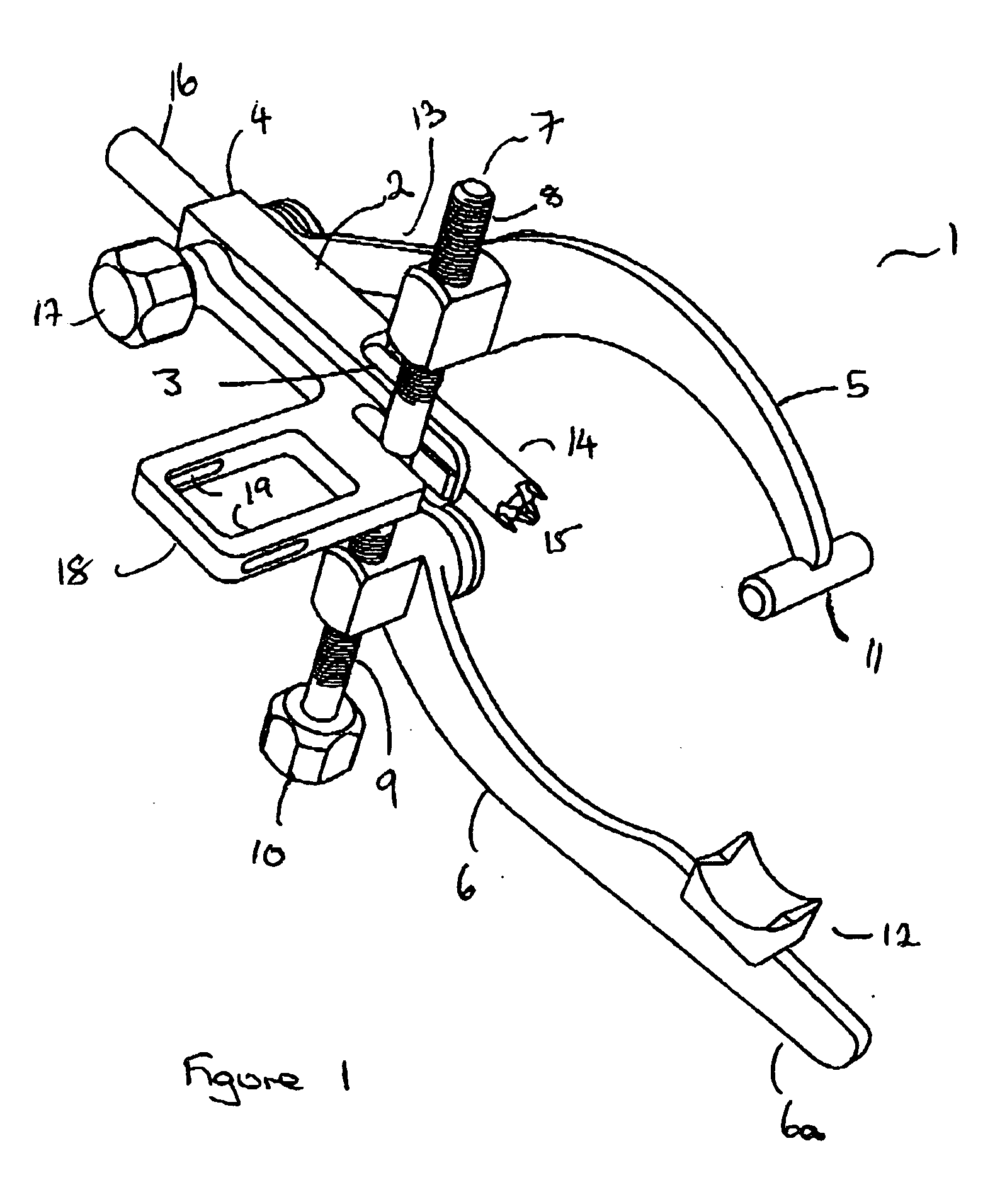
[0080] An alternative arrangement is illustrated in FIG. 3. The alignment tool 1′ of this second embodiment of the present invention comprises a support arm 2′ having a distal end 3′ and a proximal end 4′.

[0081] A superior jaw 5′ and a inferior jaw 6′ are attached to the screw means 7′ which comprises a screw member having two oppositely threaded ends 8′ and 9′ and a head 10′. When the head is rotated in one direction the jaws 5′ and 6′ move inwardly to the clamped position and when rotated in the other direction the jaws 5′ and 6′ move outwardly to the open position. During movement of the jaws they remain mutually parallel.

[0082] The jaws of this embodiment are substantially straight along at least a part of their length and are then angled such that in use their ends can interact with the neck of a femur. In the illustrated arrangement, a flag corresponding to 6a in the embodiment of FIG. 1 is not present. However, it will be understood that the arrangement of FIG. 3 could readi...


PUM


Abstract

An alignment guide for use in femoral head surgery comprising: a support member; a cannulated rod supported by, and adjustable with respect to, the support arm, and two jaws, a superior jaw and a inferior jaw, each jaw having a proximal end connected to the support, and a distal end for clamping to the neck of the femur in use; at least one of said jaws being movable from a first open position to a second clamping position.

Description

FIELD OF THE INVENTION [0001] The present invention relates to a tool for use in hip resurfacing operations. More particularly, it relates to a head alignment tool. BACKGROUND OF THE INVENTION [0002] The efficient functioning of the hip joints is extremely important to the well being and mobility of the human body. Each hip joint is comprised by the upper portion of the upper leg bone (femur) which terminates in an offset bony neck surmounted by a ball-headed portion which rotates within a socket, known as the acetabulum, in the pelvis. Diseases such as rheumatoid- and osteo-arthritis can cause erosion of the cartilage lining of the acetabulum so that the ball of the femur and the hip bone rub together causing pain and further erosion. Bone erosion may cause the bones themselves to attempt to compensate for the erosion which may result in the bone being reshaped. This misshapen joint may cause pain and may eventually cease to function altogether. [0003] Operations to replace the hip...

Claims


Application Information

Patent Timeline
IPC IPC(8): A61B17/15A61B17/16A61B17/17
CPCA61B17/175A61B17/15
Inventor TUKE, MICHAEL A.WOZENCROFT, ROBERT MICHAELSCOTT, GARETH
Owner FINSBURY DEV
Why Eureka
Try Eureka