Tool

a tool and hip technology, applied in the field of tools, can solve the problems of re-positioning affecting the function of the hip joint, and affecting the function of the hip joint, and achieve the effect of stabilising the tool

Inactive Publication Date: 2010-06-03
FINSBURY DEV
View PDF2 Cites 161 Cited by
  • Summary
  • Abstract
  • Description
  • Claims
  • Application Information

AI Technical Summary

Benefits of technology

[0036]The cannulated rod will in use enable the surgeon to position the guide wire. The cannulated rod may have a slot extending along at least a part of the length of the rod to assist in removing the tool from the guide wire once it is in position.
[0037]The cannulated rod will preferably have teeth located at the distal end thereof which in use can be driven into the surface of the femoral head. When driven into the head, these teeth help to clamp the alignment tool in position and to stabilise the tool.
[0038]The cannulated rod may additionally function as a measuring or gauging device and to assist this the surface of the rod may include measuring indica to assist the surgeon to know how deep they have cut.
[0039]An alignment rod support may be included on the support arm which may support one or more alignment rods which in use will provide a visual guide to assist the surgeon to check that the tool is in the correct position.

Problems solved by technology

Diseases such as rheumatoid- and osteo-arthritis can cause erosion of the cartilage lining of the acetabulum so that the ball of the femur and the hip bone rub together causing pain and further erosion.
Bone erosion may cause the bones themselves to attempt to compensate for the erosion which may result in the bone being reshaped.
This misshapen joint may cause pain and may eventually cease to function altogether.
Failure to do so may have the disastrous effect of allowing the machining of the cylinder of the head during the shaping procedure to “notch” into the neck of the femur.
This will predispose the bone to early failure on load bearing.

Method used


Image

  • Tool
  • Tool
  • Tool

Examples


Embodiment Construction

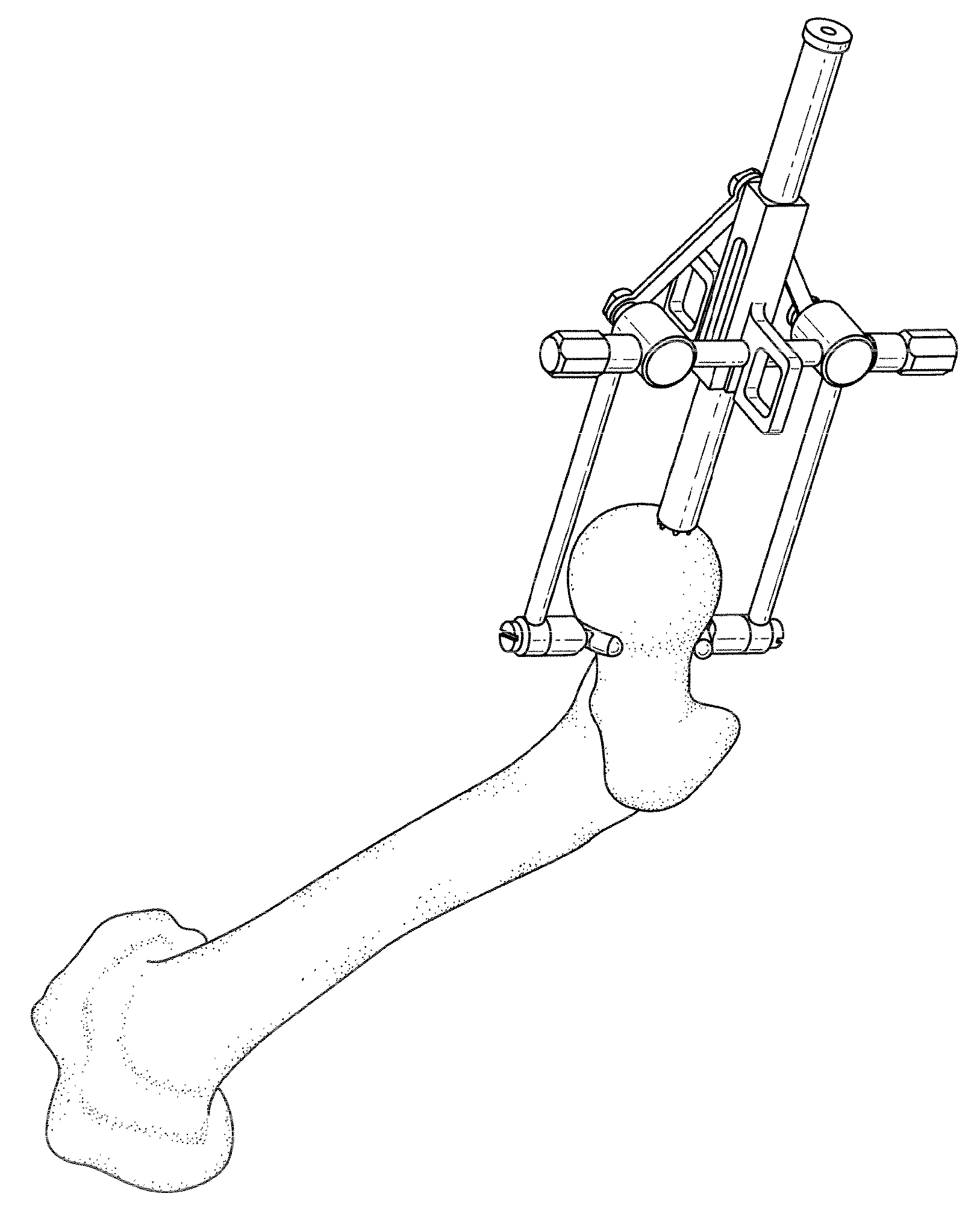
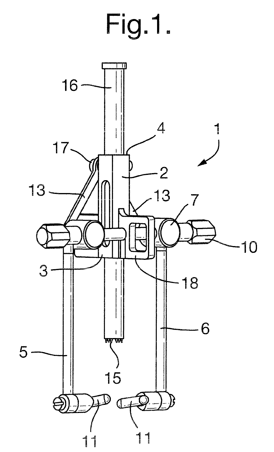
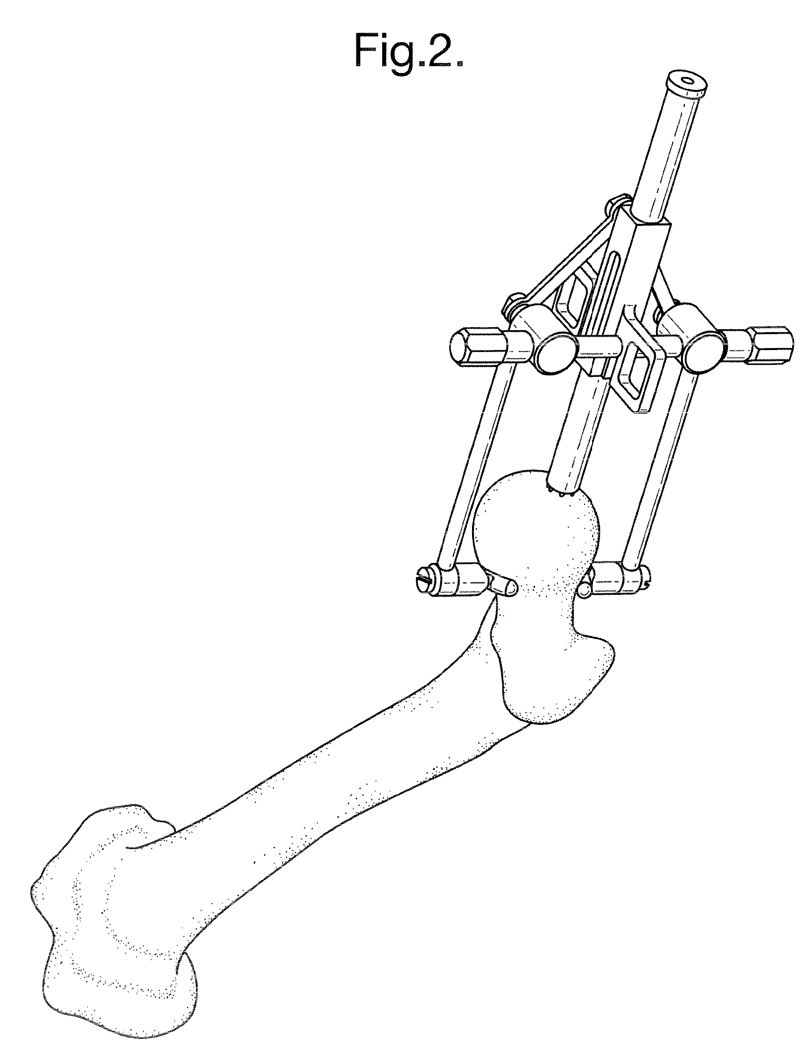
[0069]As illustrated in FIG. 1, the alignment guide 1 of one embodiment of the present invention comprises a support arm 2 having a distal end 3 and a proximal end 4.

[0070]An anterior jaw 5 and a posterior jaw 6 are attached to a screw means 7 which comprises a screw member have two oppositely threaded ends and a head 10. When the head is rotated in one direction the jaws 5 and 6 move inwardly to the clamped position and when rotated in the other direction the jaws 5 and 6 move outwardly to the open position. During movement of the jaws, they remain mutually parallel.

[0071]The jaws as illustrated are straight along a majority of its length. In an alternative arrangement, they maybe curved along at least a part of their length.

[0072]The biting means on each jaw 5 and 6 is a cylindrical curved bar 11 which is located at the end of the jaw and perpendicular thereto.

[0073]The jaws are additionally connected to the support means 2 by pivot arms 13.

[0074]The cannulated rod 16 is a sliding...


PUM


Abstract

In an alignment guide for use in femoral head surgery, a cannulated rod is supported by, and is adjustable with respect to, a support member of the alignment guide. The guide also includes two jaws, an anterior jaw and a posterior jaw, with each jaw having a proximal end connected to the support arm, and a distal end for clamping, in use, to the neck of the femur. At least one of the jaws is movable from a first open position to a second clamping position.

Description

BACKGROUND OF THE INVENTION[0001]The present invention relates to a tool for use in hip resurfacing operations. More particularly, it relates to a head alignment tool.[0002]The efficient functioning of the hip joints is extremely important to the well being and mobility of the human body. Each hip joint is comprised by the upper portion of the femur which terminates in an offset bony neck surmounted by a ball-headed portion which rotates within a socket, known as the acetabulum, in the pelvis. Diseases such as rheumatoid- and osteo-arthritis can cause erosion of the cartilage lining of the acetabulum so that the ball of the femur and the hip bone rub together causing pain and further erosion. Bone erosion may cause the bones themselves to attempt to compensate for the erosion which may result in the bone being reshaped. This misshapen joint may cause pain and may eventually cease to function altogether.[0003]Operations to replace the hip joint with an artificial implant are well-kno...

Claims


Application Information

Patent Timeline
Patent Type & Authority Applications(United States)
IPC IPC(8): A61B17/56
CPCA61B17/175A61B17/15
Inventor TUKE, MICHAEL ANTONYTAYLOR, ANDREW CLIVESPENCER, JOHN DAVID
Owner FINSBURY DEV
Why Eureka
Try Eureka