Illuminating rail system

a technology of illumination rails and buffer rails, applied in the direction of lighting support devices, vessels, instruments, etc., can solve the problems of limited use of conventional buffer rails, and achieve the effect of improving the noticeability of boats

Inactive Publication Date: 2005-11-10
KWON YOUNG CHUL
View PDF6 Cites 9 Cited by
  • Summary
  • Abstract
  • Description
  • Claims
  • Application Information

AI Technical Summary

Benefits of technology

[0004] The present invention is contrived to overcome conventional disadvantages. Accordingly, it is an object of the present invention is to provide an illuminating rail system to realize an utmost ext...

Problems solved by technology

In a practical point of view, however, the utility of the conventional buffer rails ...

Method used


Image

  • Illuminating rail system
  • Illuminating rail system
  • Illuminating rail system

Examples


Embodiment Construction

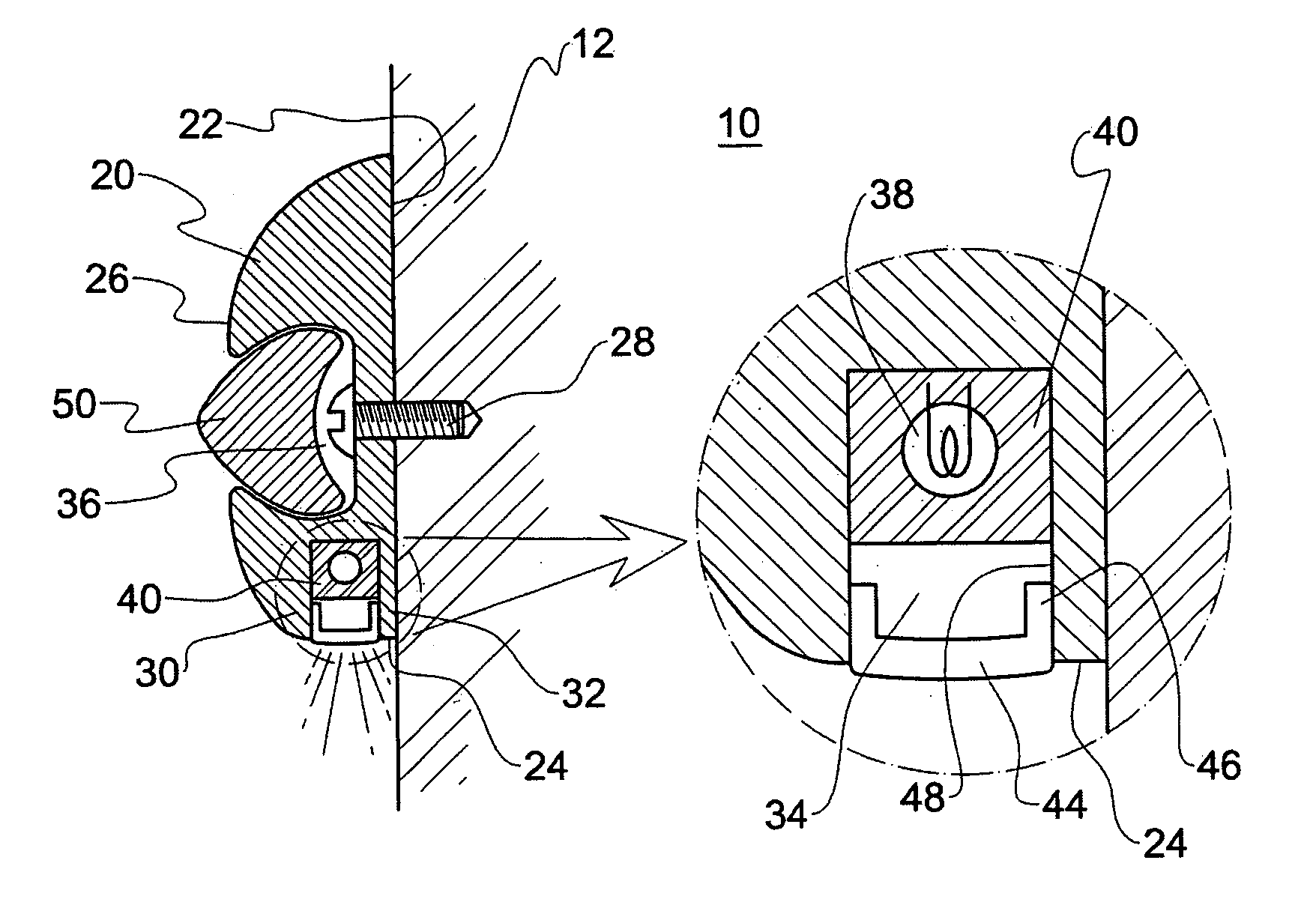
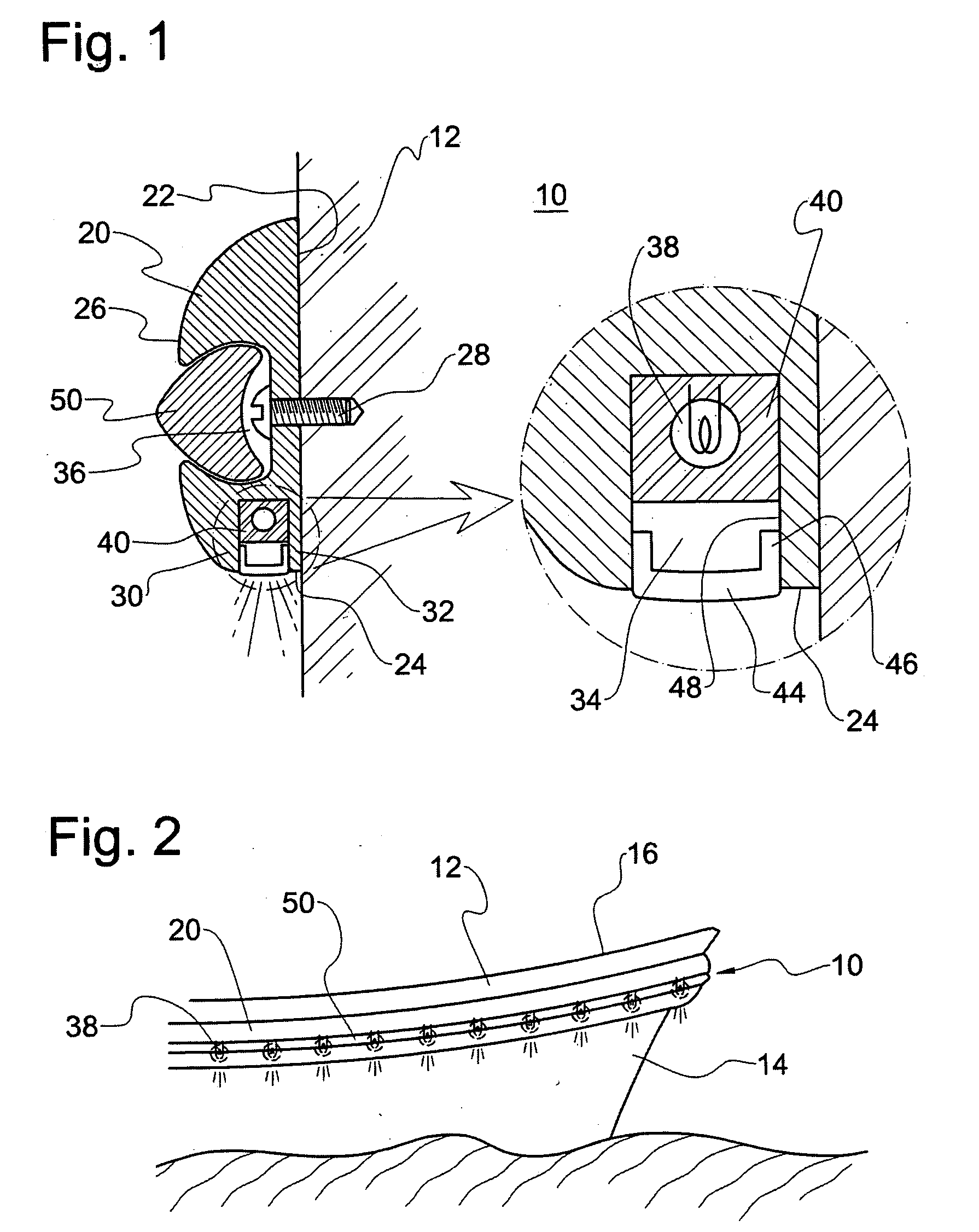
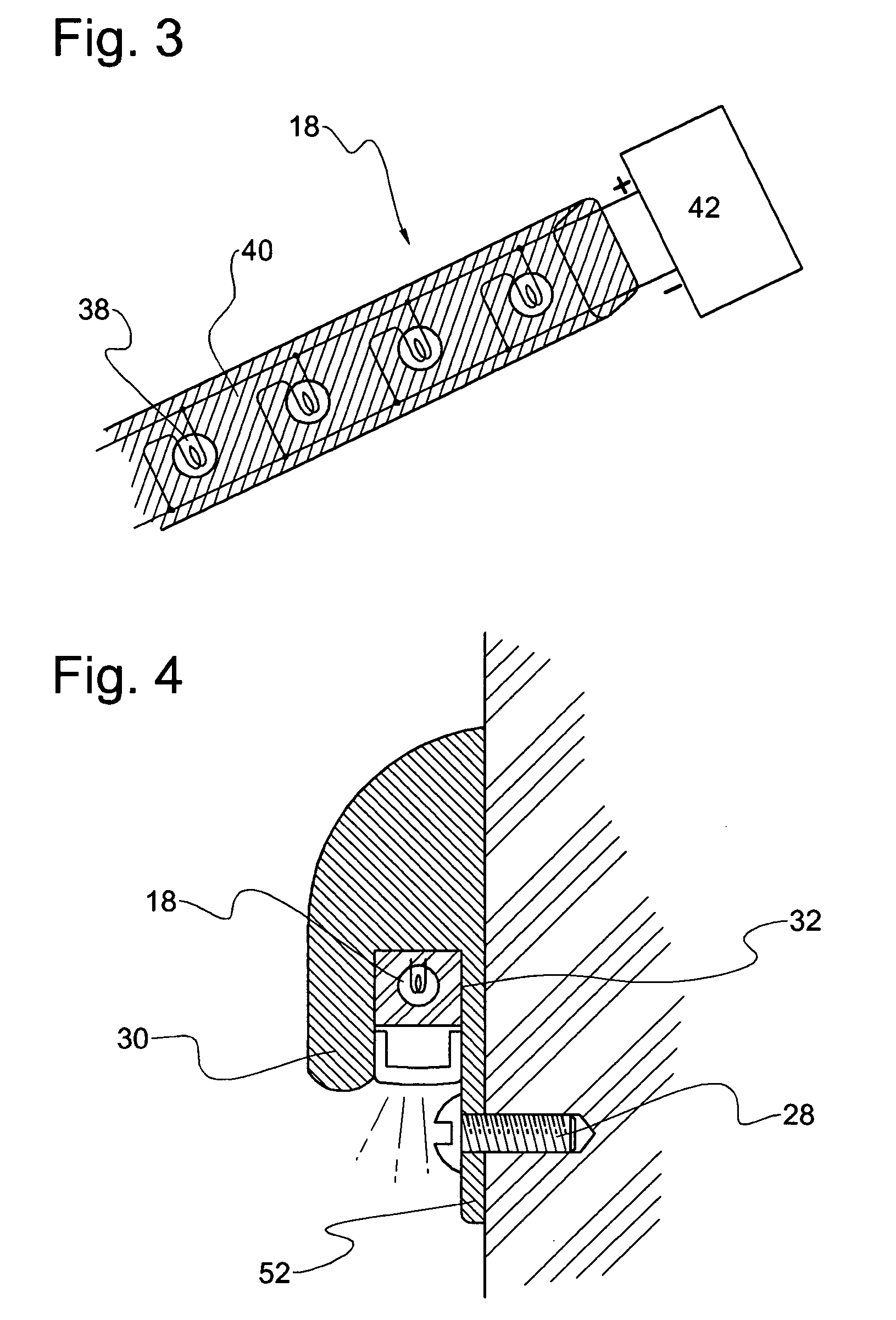
[0016]FIG. 1 shows a preferred embodiment of an illuminating rail system 10 attached on a wall 12 outside the system 10. As shown in FIG. 2, the wall 12 is preferably an external portion 14 of a boat 16. FIG. 3 shows an illuminator 18 in FIG. 1. As shown therein, the illuminating rail system 10 comprises a rail 20 defined by an elongate rear surface 22, an elongate bottom surface 24 and an elongate front surface 26.

[0017] The rear surface 22 in a substantially vertical formation is attached to the wall 12 outside the system 10 by an attachment member 28 such as screws. The bottom surface 24 is upwardly recessed to define along the rail 20 a front panel 30, a rear panel 32, and a furrow 34 between the front and rear panels 30, 32. In an embodiment, the front surface 26 is also substantially recessed toward the rear surface 22 to form an elongate opening 36 along the rail 20.

[0018] According to this construction, the rail 20 is attached on the wall 12, for example, of boats and yach...


PUM


Abstract

An illuminating rail system comprising a rail defined by an elongate rear surface and an elongate bottom surface, the rear surface attached to a wall outside the system, the bottom surface upwardly recessed to define along the rail a front panel, a rear panel, and a furrow between the front and rear panels, with an elongate illuminator retained in the furrow.

Description

BACKGROUND OF INVENTION [0001] The present invention relates to a multi-purpose rail. More particularly, the present invention relates to an illuminating rail system attachable to an exterior of a boat, for example, to realize an utmost external decoration and esthetic illumination. [0002] An increasing number of boats carry buffer rails also called rub rails on their exterior to minimize damage from bumping with another boat on the waters. Buffer rails on the market are also expected to carry durability and fade resistance. Such conventional buffer rails simply serve as no more than external attachments for boat protection from possible external impacts. In a practical point of view, however, the utility of the conventional buffer rails is limited to marina where bumping with other boats are usually recorded minimal in damage. [0003] A demand on this market is to enable the buffer rails to serve as decorative tools for the boat day and night on the waters. Another demand is to comb...

Claims


Application Information

Patent Timeline
IPC IPC(8): B60P7/02B63B45/04B63B59/02
CPCB63B45/04B63B59/02
Inventor KWON, YOUNG
Owner KWON YOUNG CHUL
Why Eureka
Try Eureka