
System, method and computer program for vote tabulation with an electronic audit trail

a voting system and computer program technology, applied in the field of tabulation of votes, can solve the problems of difficult to achieve the same tally, many ballots were deemed ‘spoiled’ or ‘blank’, and the interpretation process of what constitutes a vote mark has always been prone to inconsistencies, so as to achieve cost savings, and ensure the integrity of the process. the effect of integrity

Active Publication Date: 2005-11-10
DOMINION VOTING SYST CORP
View PDF3 Cites 48 Cited by
  • Summary
  • Abstract
  • Description
  • Claims
  • Application Information

AI Technical Summary

Benefits of technology

[0025] The computer also includes a suitable back-Lip storage device and related utilities to reduce the risk of data loss from the memory.
[0027] One aspect of the present invention is that the association of the vote stamp with the corresponding digital image enables rapid and cost effective verification of the integrity of the processes. For example, a random selection of a defined percentage of ballots processed in accordance with the invention can be examined for accurate collection of voter intent by calling up from the central memory the digital images and corresponding vote stamps. (for example from ballots received in a particular polling station) and by comparing the digital image displayed on a computer screen with the results of the processing thereof as shown by the data included in the vote stamp.
[0029] One object of the present invention is to provide a system and method that enables an electoral process that can be audited efficiently, accurately and transparently.

Problems solved by technology

One of the challenges in permitting efficient verification of voting results, and also demonstration of the integrity of the vote, are the subjective elements generally involved in determining voter intent.
A set of candidates and their agents rarely share common motivation and accordingly the interpretation process of what constitutes a mark on a ballot has always been prone to inconsistencies.
This fact generally makes it difficult to achieve the same tally when counting the same ballots multiple times, as there is no assurance that any given ballot would be interpreted the same way by every interested party.
In addition, many ballots were deemed ‘spoiled’ or ‘blank’ because the voter (either intentionally or unintentionally) made too many or too few marks on the ballot.
The Mechanical Based Systems have been deemed susceptible to inconsistencies in well publicized cases.
For example, some mechanical punch systems have been shown to leave cut-out ‘chads’ partially attached, leading to disputes surrounding election results.
Also, in the case of Mechanical Based Systems and Optical-Mark Based Systems, the objective standards for what constitutes an indication of voter intention are generally set by the manufacturer of the voting device and have not been adaptable to conform to objective standards determined by election officials for a particular vote.
These concerns have hindered the ability to verify vote results, and have generally had a negative impact on impressions of vote integrity.
However, it is well known that processing errors, computer memory corruption or computer memory loss can occur in digital devices and there have been well publicized reports suggesting that this may be the case with some prior art DRE systems.
If this type of failure were to occur, voter intention is permanently corrupted or lost and a new election would have to be held.
In addition to the aforesaid disadvantages, the prior art solutions generally do not enable an election official to effectively audit voting results and / or verify the integrity of the vote.
For example, the above mentioned prior art technologies do not permit an election official to pick a ballot at random and examine the results of the optical scan algorithms that determined voter intent.

Method used


Image

  • System, method and computer program for vote tabulation with an electronic audit trail
  • System, method and computer program for vote tabulation with an electronic audit trail
  • System, method and computer program for vote tabulation with an electronic audit trail

Examples


Embodiment Construction

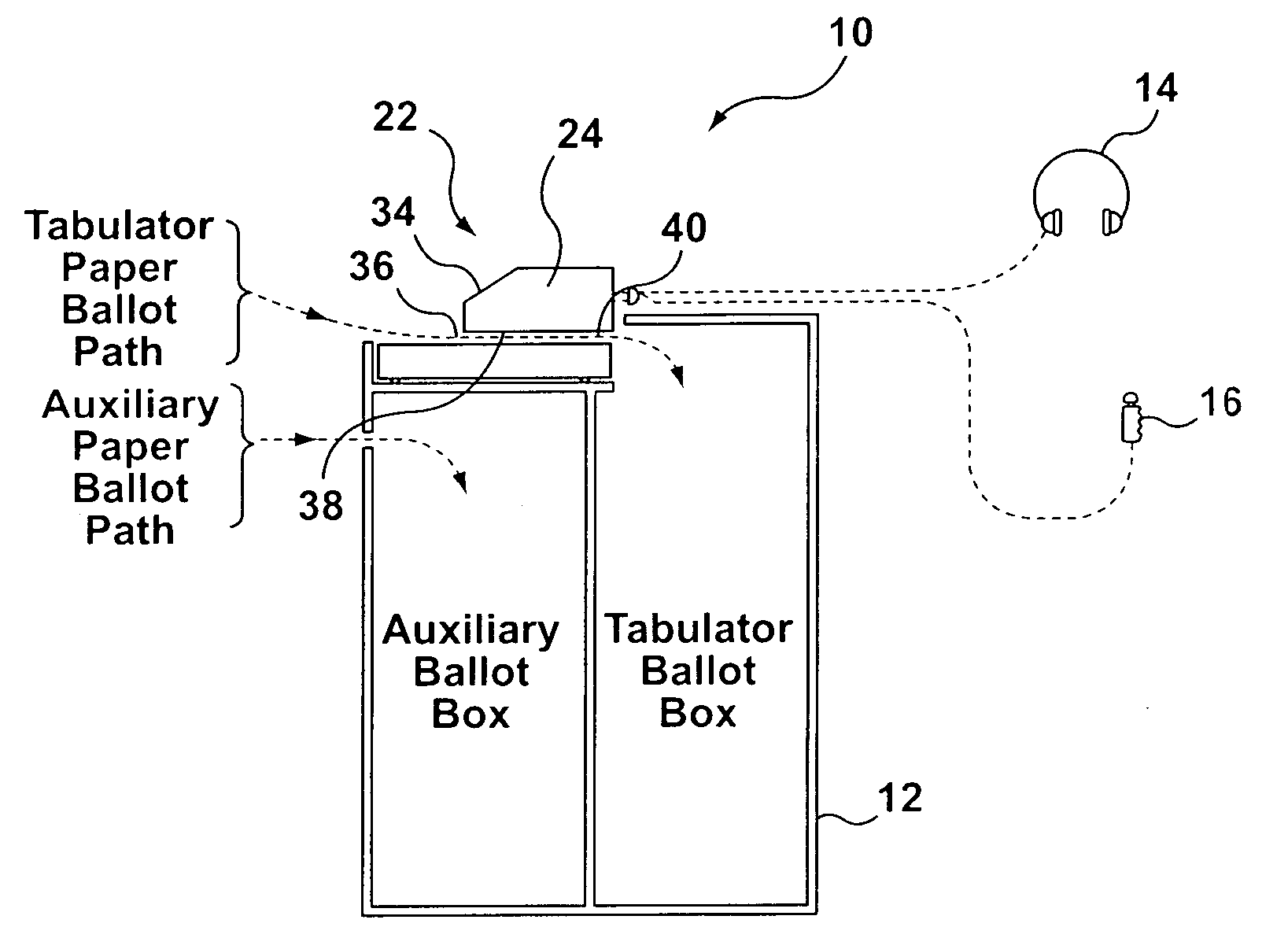
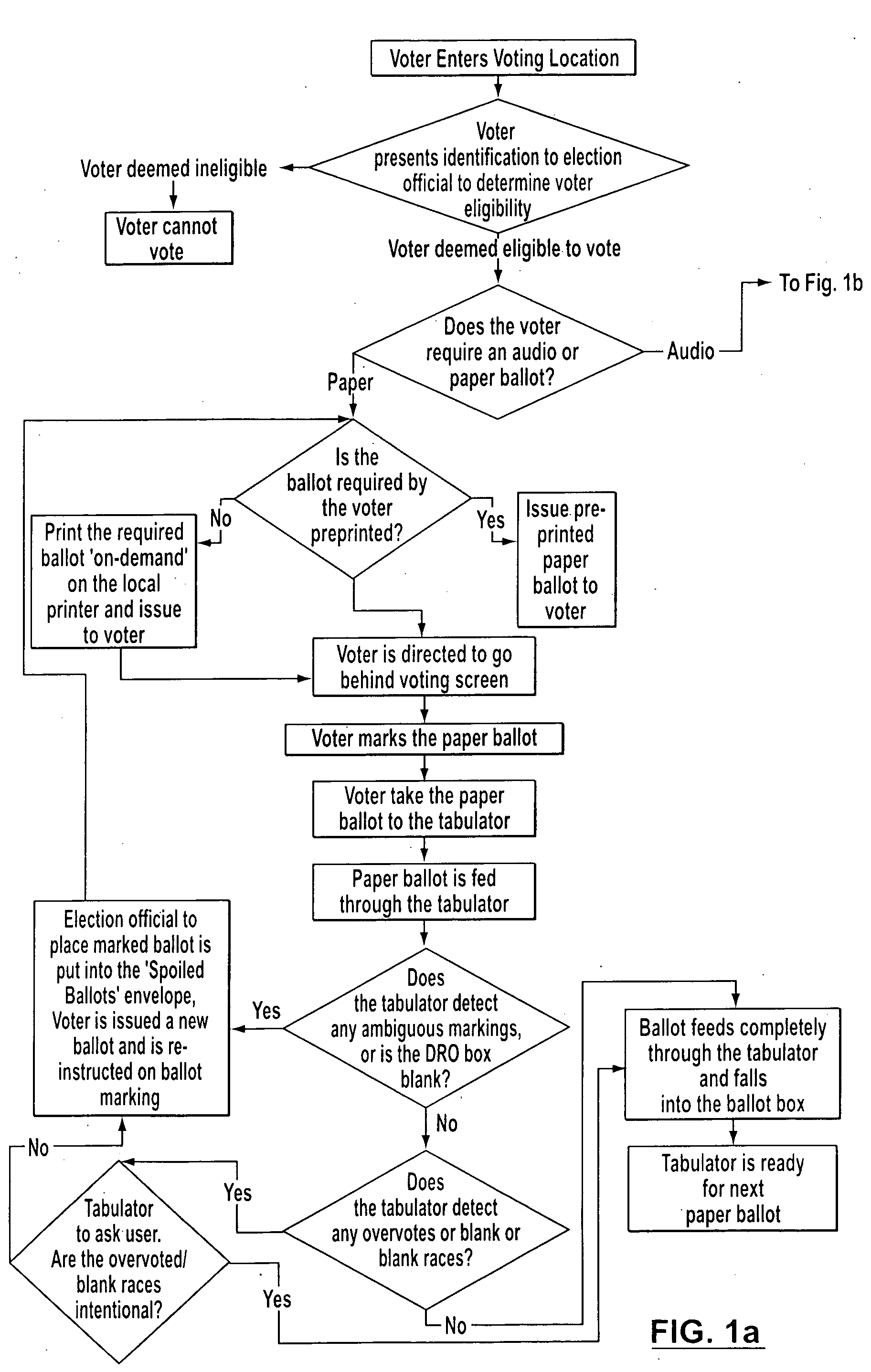
[0039] One aspect of the present invention is a method that includes the following steps: [0040] 1. Establishing one or more criteria for analyzing a plurality of paper ballots, the paper ballots including one or more voter selection areas, which criteria include threshold values for determining whether a particular voter selection area has been filled in, has not been filled in, or it is ambiguous whether or not it has been filled in; [0041] 2. Scanning at least one of the paper ballots using a scanning device, the scanning device generating a digital image document of the each paper ballot; [0042] 3. Analyzing the digital image document to determine whether a particular voter selection area has been filled in, has not been filled in, or is ambiguous as to whether or not it has been filled in, so as to define a series of processing results for each digital image; [0043] 4. Creation of a vote stamp which includes the processing results and attaching the vote stamp to the digital ima...


PUM


Abstract

A system, method and computer program for tabulating votes and creating an audit trail is provided. A ballot processing device is integrated with a ballot box. The ballot processing device includes a paper feed mechanism, a computer, a ballot processing application loaded on the computer, and a digital scanning device linked to the computer. The ballot processing application provides instructions to the computer to initiate the digital scanning device to scan a paper ballot fed into the paper feed mechanism so as to create a digital image of the paper ballot. The ballot processing application also processes the digital image to establish a series of processing results defining one or more voting results for the paper ballot, and also an audit trail. The ballot processing application processes the digital image to define the voting results based on criteria established by election officials. The audit trail enables election officials to verify that particular paper ballots have been processed correctly in accordance with these criteria.

Description

FIELD OF INVENTION [0001] This invention relates generally to technologies for tabulating votes. This invention relates more particularly to ballot boxes with vote tabulation capabilities. The invention also relates to method for tabulating votes in an election. BACKGROUND OF THE INVENTION [0002] Numerous voting technologies are known. These technologies are generally directed to permitting votes to be recorded with efficacy while maintaining the secrecy of the ballot. [0003] One category of voting technology involves the use of the paper ballot. Various methods exist for collecting and tabulating votes recorded by paper ballots. Prior art has been created to rely on paper ballots while using modern digital technology. For example, “Optical-mark Based Systems” allow voters to mark paper ballots and feed the ballots through an automated optical ballot scanning tabulator into sealed ballot boxes. The optical scanning technology determines the nature of the vote and the computer techno...

Claims


Application Information

Patent Timeline
Patent Type & Authority Applications(United States)
IPC IPC(8): G06K9/80G07C13/00
CPCG06Q20/382G07C13/00G06Q20/401
Inventor POULOS, JOHNHOOVER, JAMESIKONOMAKIS, NICKOBRADOVIC, GORAN
Owner DOMINION VOTING SYST CORP
Learn More