Reading apparatus for bar code on a test tube

Inactive Publication Date: 2005-11-10
IDS CO LTD
View PDF12 Cites 72 Cited by
  • Summary
  • Abstract
  • Description
  • Claims
  • Application Information

AI Technical Summary

Benefits of technology

[0012] In the bar code reading apparatus according to the present invention, a test tube is r

Problems solved by technology

As a result, the test tube 1 is also inclined

Method used


Image

  • Reading apparatus for bar code on a test tube
  • Reading apparatus for bar code on a test tube
  • Reading apparatus for bar code on a test tube

Examples


Embodiment Construction

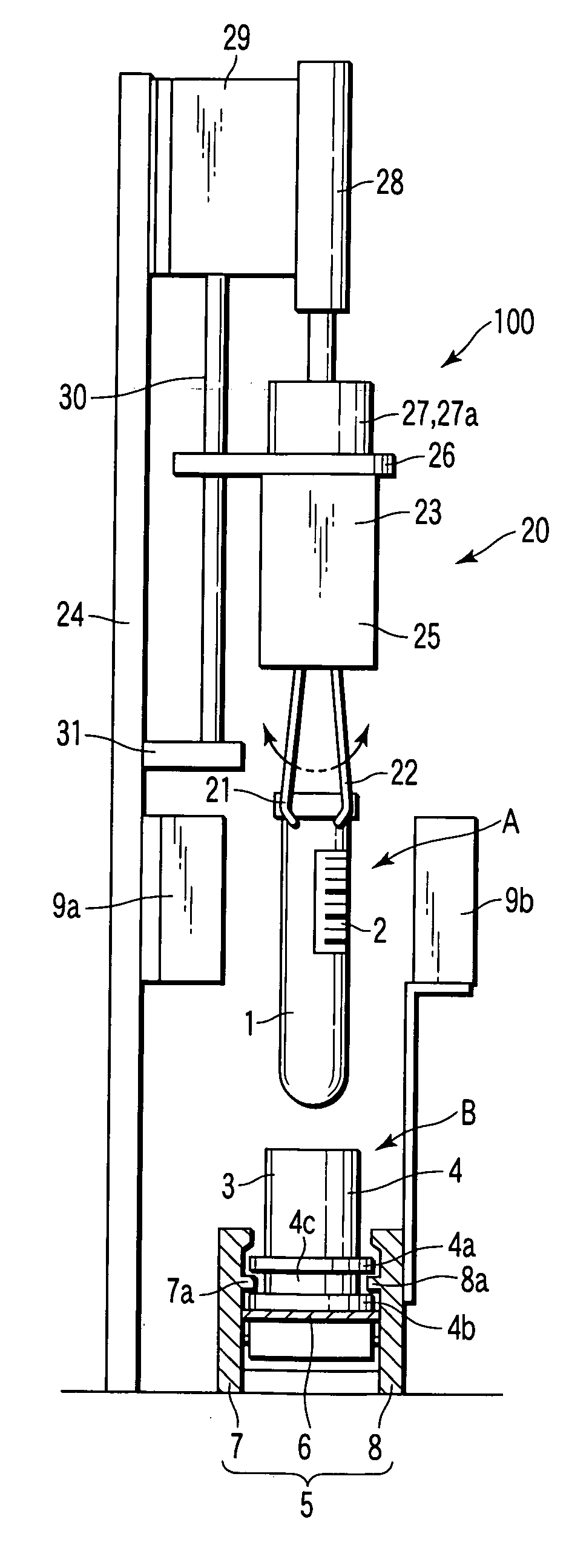
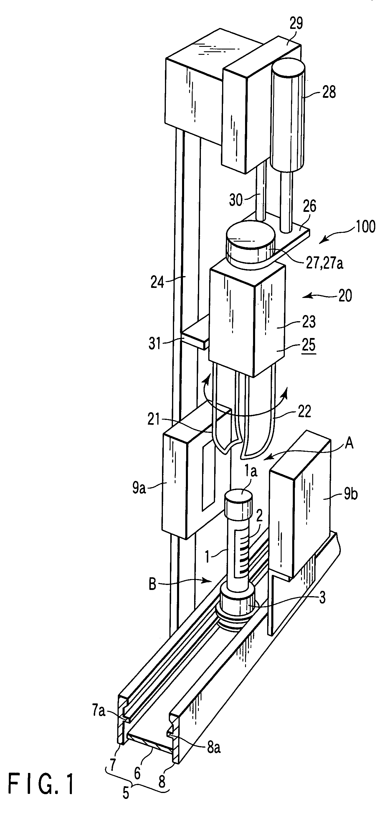
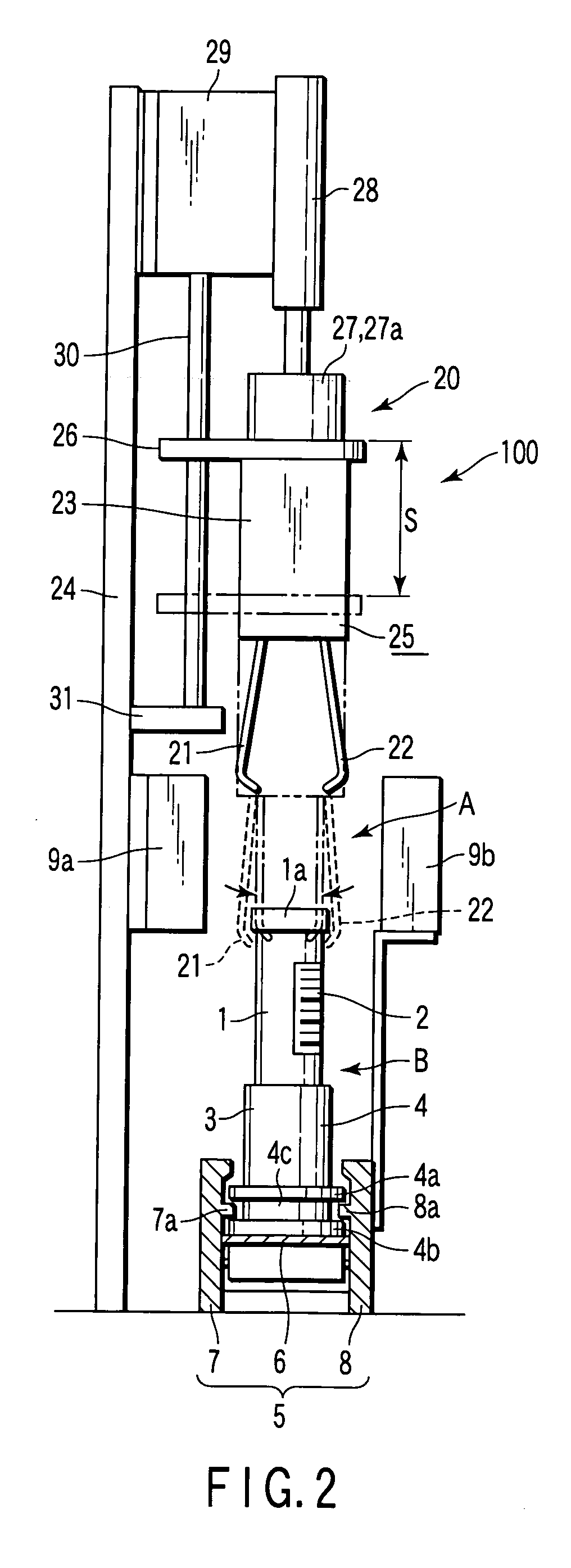
[0025] A bar code reading apparatus 100 according to an embodiment of the present invention will be explained with reference to FIG. 1 to FIG. 3. The bar code reading apparatus 100 is an apparatus to read a bar code 2 affixed to a test tube 1. The test tube 1 contains a sample such as blood, and the upper end port is closed with a plug 1a. The test tube 1 is conveyed on a conveying path 5 in the state of standing vertically in a test tube holder 3. The conveying path 5 is provided in a part of a unit which automatically analyzes the contents of the test tube 1.

[0026] The test tube holder 3 has a cylindrical part 4 to insert the test tube 1. The cylindrical part 4 has a pair of flanges 4a and 4b in two steps on the lower periphery. A circular groove 4c is formed between the flanges 4a and 4b. The cylindrical part 4 has a leaf spring inside to hold vertically the inserted test tube 1. The conveying path 5 is composed of a belt conveyor 6 and guide rails 7 and 8.

[0027] The belt conve...


PUM


Abstract

A bar code reading apparatus has a reader and a test tube handling mechanism. The reader is provided on the side of a bar code reading position set above on the way of a conveying path, and reads a bar code of a test tube. The test tube handling mechanism is placed above the bar code reading position. The test tube handling mechanism descends to grab a test tube held by a test tube holder stopped at a test tube lifting position set right below the bar code reading position, and ascends to draw out the grabbed test tube from the test tube holder. The test tube handling mechanism faces a bar code of a test tube by rotating a lifted test tube.

Description

CROSS-REFERENCE TO RELATED APPLICATIONS [0001] This application is based upon and claims the benefit of priority from the prior Japanese Patent Application No. 2004-129780, filed Apr. 26, 2004, the entire contents of which are incorporated herein by reference. BACKGROUND OF THE INVENTION [0002] 1. Field of the Invention [0003] The present invention relates to an apparatus for reading a bar code affixed to a test tube, which is provided on the way of a conveying path for automatically conveying test tubes. [0004] 2. Description of the Related Art [0005] A test tube containing a sample such as blood is labeled a bar code including information about the sample, such as components of the sample, liquid level of principal component, and volume of the contents. The bar code is detected with a reading apparatus provided on the way of a conveying path for automatically conveying the test tube. The information read with the reading apparatus is sent to a unit provided on the downstream side....

Claims


Application Information

Patent Timeline
IPC IPC(8): G01N35/00G06K7/015G01N35/04G06K7/10G06K17/00
CPCG01N35/00732G06K2017/009G06K7/10861G01N2035/00752G06K7/10
Inventor ITOH, TERUAKI
Owner IDS CO LTD
Why Eureka
Try Eureka