
Direct drive for a cylinder

Inactive Publication Date: 2005-11-10
SIEMENS AG
View PDF1 Cites 7 Cited by
  • Summary
  • Abstract
  • Description
  • Claims
  • Application Information

AI Technical Summary

Benefits of technology

[0008] To increase operating reliability, however, it may be expedient for the hollow shaft to be mounted preferably in the drive housing.
[0009] Advantageously, the drive housing is connected to a frame element by means of a supporting element. Further space can thereby be saved.
[0010] Advantageously, the drive housing is connected directly to the frame element. This embodiment makes it possible, in particular, to arrange drives according to the invention and the cylinders driven by them so as preferably to be stacked one above the other.
[0018] Advantageously, the hollow shaft is designed in such a way that the direct drive is preheated by means of the auxiliaries and / or fuels to be supplied to the cylinder. Thus, the direct drive can be brought quickly or cost-effectively to operating temperature.

Problems solved by technology

Known drive concepts require a relatively large amount of space, particularly because of the use of coupling devices, and are susceptible to faults, above all, when employed in the paper industry.

Method used


Image

  • Direct drive for a cylinder
  • Direct drive for a cylinder
  • Direct drive for a cylinder

Examples


Embodiment Construction

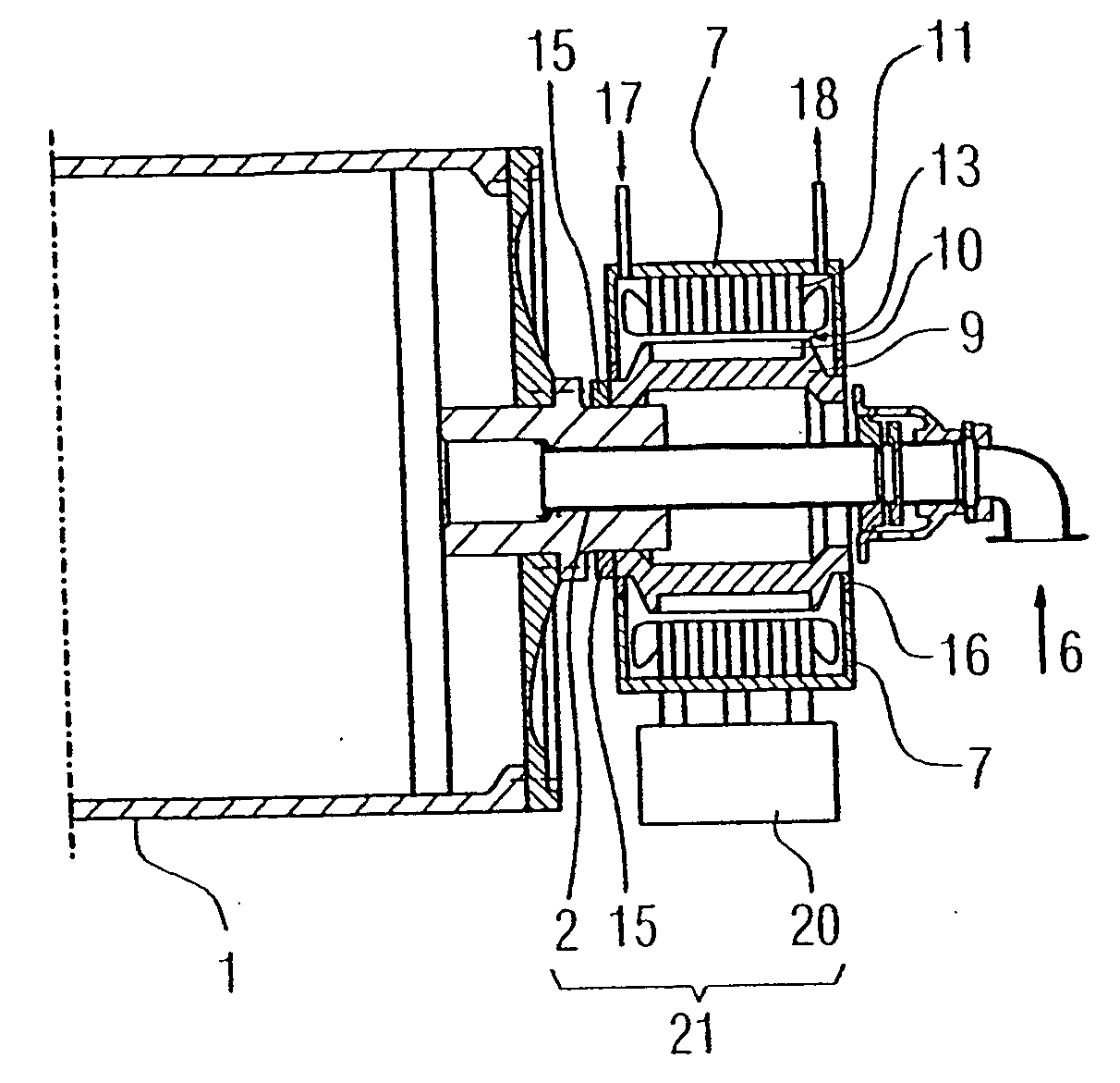
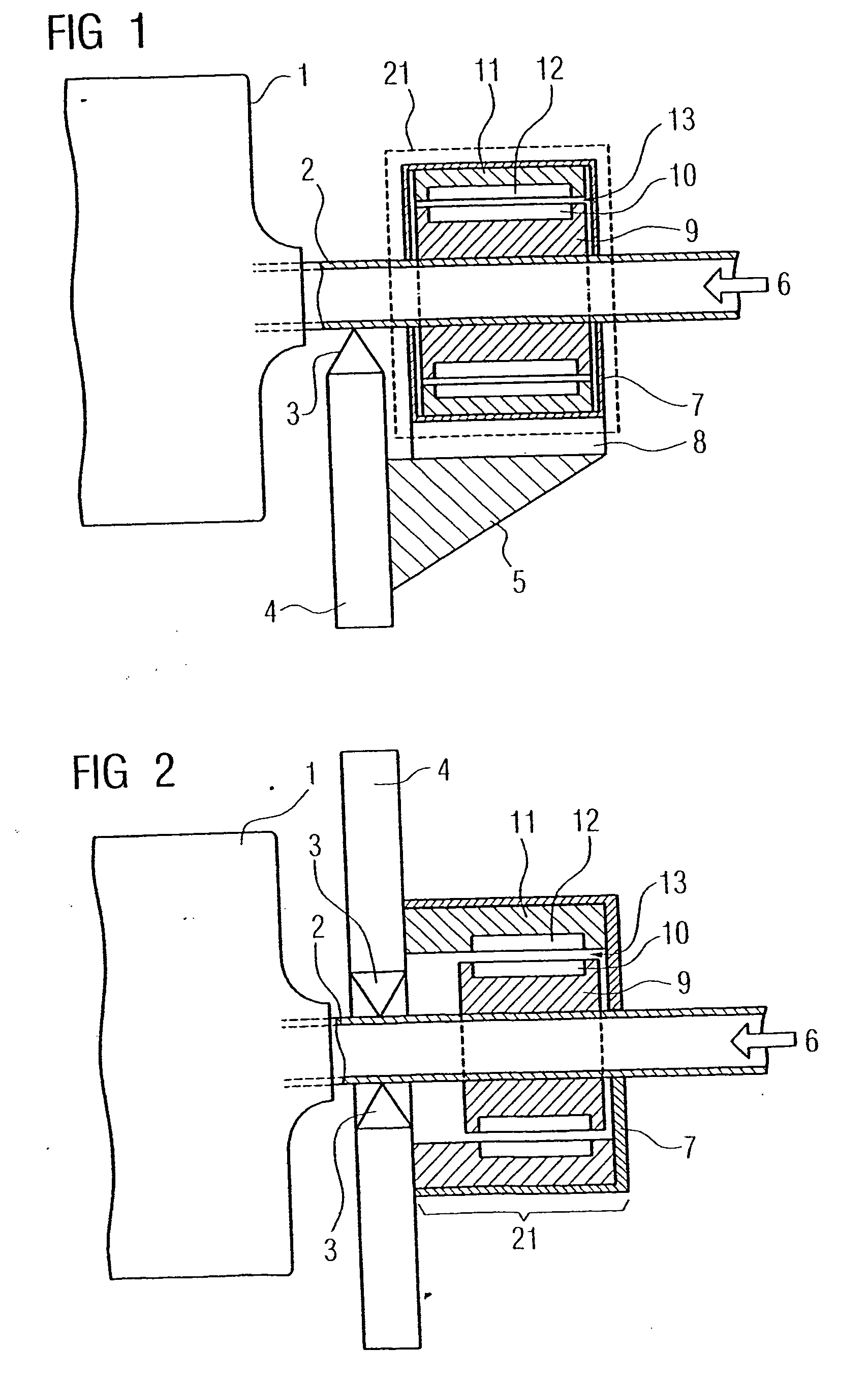
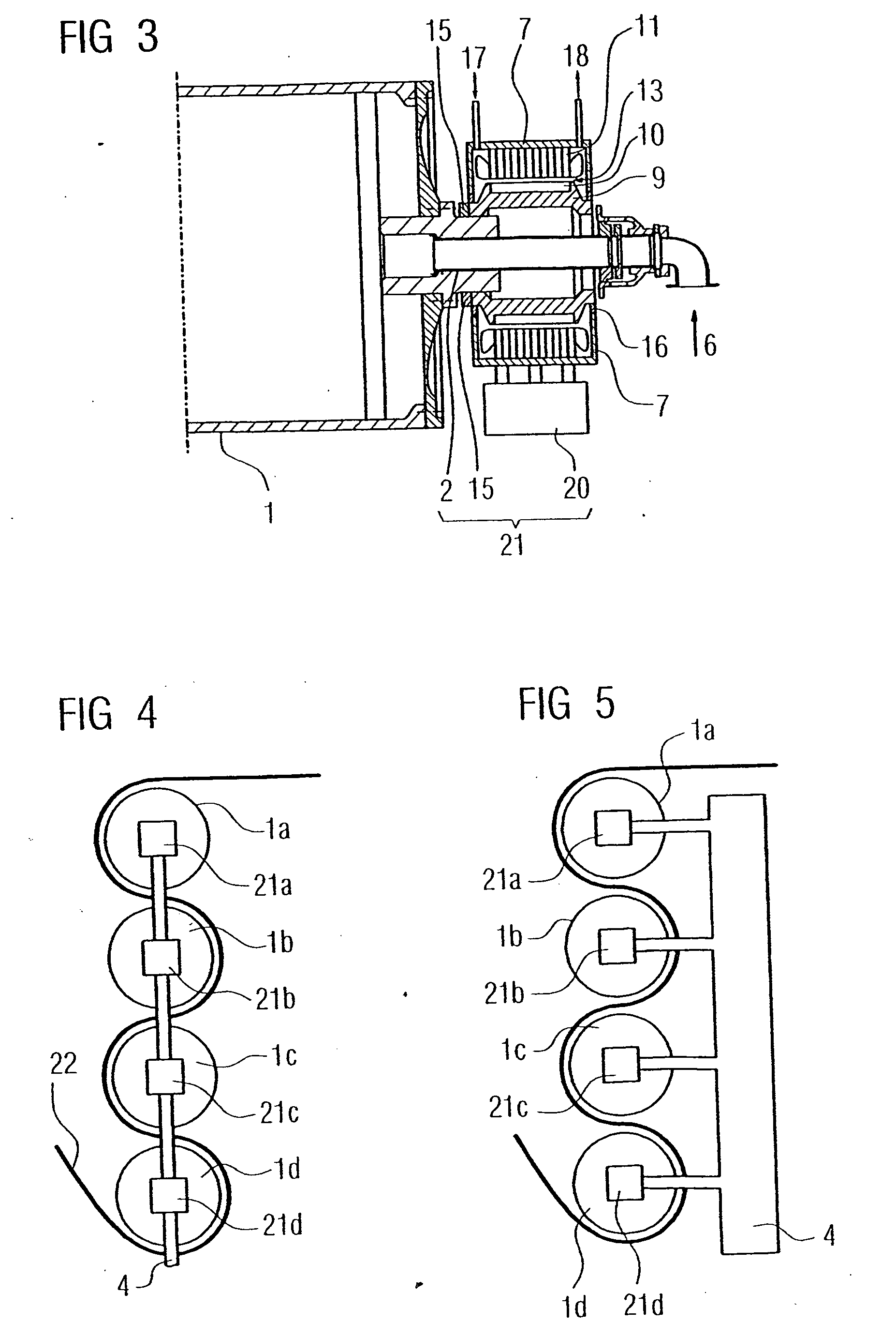
[0026]FIG. 1 shows a direct drive 21 for a cylinder 1. A hollow shaft 2 in this case coincides at least partially with the cylinder axis. The cylinder 1 is in this case illustrated in the drawing only as a partial outline. A bearing device 3 arranged on a frame element 4 serves for holding the cylinder 1 by means of the hollow shaft 2.

[0027] The hollow shaft 2 is connected fixedly to the cylinder 1 and performs preferably three functions: [0028] 1. Mounting of the cylinder 1 in conjunction with the bearing device 3, [0029] 2. Drive or rotation of the cylinder 1 with the aid of the drive device 21, and [0030] 3. Supply and / or discharge 6 of auxiliaries or fuels into and / or out of the cylinder 1.

[0031] With regard to the supply and / or discharge 6 of auxiliaries or fuels, auxiliaries and / or fuels, such as oil, water, steam or air, can be supplied to the cylinder and / or the pressure of the cylinder can be regulated. Fuels supplied may also be hydraulic oil or coolant. Steam is supplie...


PUM


Abstract

A direct drive (21) for a cylinder (1) comprises a hollow shaft (2). The direct drive comprises a drive housing (7) in which at least one rotor device (9) and at least one stator device (11) are arranged. According to the invention, the stator device (11) is connected to the drive housing (7), auxiliary substances and / or operating substances such as oil, coolant or vapour are supplied to the cylinder (1) through the hollow shaft, the hollow shaft (2) is guided through the drive housing (7) preferably without bearings, and the rotor device (9) is directly connected to the hollow shaft (2). The inventive drive (21) is especially maintenance-free and compact and especially used for a rotating cylinder (1) in the paper industry, without gearboxes and clutches, and with direct supply or discharge of auxiliary substances and / or operating substances. The rotor device (9) at least partially surrounds the hollow shaft (2).

Description

CROSS REFERENCE TO RELATED APPLICATION [0001] This application is a continuation of copending International Application No. PCT / DE03 / 03565 filed Oct. 27, 2003 which designates the United States, and claims priority to German application no. 102 52 110.7 filed Nov. 8, 2002.TECHNICAL FIELD OF THE INVENTION [0002] This invention relates to a direct drive for a cylinder with a hollow shaft, the direct drive having a drive housing, inside which are arranged at least one rotor device and at least one stator device, the stator device being connected to the drive housing. DESCRIPTION OF THE RELATED ART [0003] In the basic materials industry, material webs, which may consist preferably of paper or else of plastic, aluminum or similar materials, are moved or processed with the aid of cylinders. Preferably cylinders of this type are designed as rotating rollers. At the present time, cylinders of this type, such are used, for example, in the paper industry, are driven by means of a motor, the m...

Claims


Application Information

Patent Timeline
IPC IPC(8): D21F5/02D21F7/02H02K5/16H02K7/00H02K7/14
CPCB65H2404/162D21F5/021H02K7/14H02K5/163H02K7/003D21F7/02
Inventor KRAUSE, ANDREASLIEPOLD, HELMUTWEBER, DIETER
Owner SIEMENS AG
Features
  • Generate Ideas
  • Intellectual Property
  • Life Sciences
  • Materials
  • Tech Scout
  • Unparalleled Data Quality
  • Higher Quality Content
  • 60% Fewer Hallucinations
Learn More